After a few more summits, I’ve decided my SOTA getup needs serious work. The amateur radio community largely acts on instinct and legend, so I’d figure I actually do the math in creating an ultimate SOTA antenna.
Part 1 will cover everything pertinent to coaxial cable - the weight, losses, wavelength dependence, and network parameters.
Introduction
I want you to close your eyes. Peek a little at a time to read if you have to or have someone read this part aloud. Eyes closed? Ok. Picture what comes to mind when I say “Ultimate SOTA Antenna.” What shape is it? Frequency? Transmit power? Really focus on the little things and especially what makes it better than your current QRP setup.
Open your eyes. Let’s compare the big picture:
Requirements for “The Ultimate SOTA Antenna”
Construction
- Lightweight without complicated guy lines or solid tubes (save a fiberglass mast)
- Sets up quickly and stays up - no fuss
- No snagging on trees or getting stuck between rocks
Performance
- Has ideal SWR without a tuner
- Continuous DX the moment it’s online
- Maximum radiation efficiency - current concentrated at the highest point
In all, you want a simple antenna that does its limited job very well. What does this antenna actually look like? I’m going to say a single-band, half-wavelength dipole.
Defense
I know operators with multi-band-hopper-balun-h-network-end-fed-traps are arming themselves with pitchforks at this very moment. I would too, considering I built my own end-fed not too long ago, and have a 1.2 SWR dipole in the backup gear bag. I’ve tried quite a few approaches, but the single-band dipole is the way to go.
I cannot explain how often I’ve waited for contacts on summits in thunderstorms, high wind, and miserable conditions while I read around of 100s of contacts other operators’ experiences. I’ve had to schedule or spot nearly every contact pushing 10W with the KX2 on CW. It’s pitiful, really. I need to trust my equipment on long hauls and need to enjoy setting it up each time - there is nothing simpler than a fine-tuned resonant single-element dipole.
I know mechanical linkages are a thing on multi-band dipoles. But they get snagged. I almost exlusively operate on 20M unless I’ve had a long day and am operating closer to sunset, and find that I want something to work every time. If that means one frequency, so be it. The efficency of a single resonant contact will net me more contacts than a poorly designed double-band system.
With the way the solar cycle looks and the normal schedule of a mountaineer (off the summit by 12pm) 20M is my frequency of choice.
Approach
I want to break down every piece of a SOTA setup. More importantly, I want to actually do the math and test behind every piece of equipment. Much of the hobby is based on superstition - a balun must be used here, a choke here, orient the antenna in this direction, measure this with an extra 6 inches. This guide should tell you exactly what to do and the math to prove it.
With the ideal antenna being a 20M resonant half-wavelength dipole, there are several pieces to consider:
- The coax running to the masthead
- The masthead - its weight, construction, connectors
- The balun - often a 1:1 balun is preached as necessity, but I’d like to do the math to see if it really is.
- The antenna wire itself - what material, diameter, length , and angle?
- The insulator and guy lines - much supersition around this topic with skin effect and velocity factor of nylon
So, without further ado, the humble coax cable.
Coax: Weight
The biggest reason not to use coax is weight. It gets tangled if not coiled properly, and requires that a mast setup have both a masthead and cable weighing on the fiberglass mast to pull it down.
Remember our coax length will be a maximum of 40 feet. I’ve never seen hikeable masts longer than 30ft, and mine comes in 20 ft.
Types of Coaxial Cable
RG-58
The standard for any radio, lab, or short-distance setup is 50-ohm RG-58. This specification document gives these parameters:
- Impedance: 53.5 Ohms
- DB/100ft: 1.17 (source says 1.5)
- Propagation Velocity: 65.9 % of lightspeed
- Weight: 37g/m
RG-58 is so widely used because it’s so widely used. The link distance for a SOTA setup is shorter than most, so we can theoretically use a cable with a fair amount more loss without more repercussions. Allow me to introduce:
RG-174
RG-174 is the standard for short-distance SMA connections because of its thin, flexible nature. Here are the specifications:
- Impedance: 50 Ohms
- Db/100ft: < 8.4 (this source gives 4.54 dB)
- Propagation Velocity: 66%
- Weight: 13.38 g/m
Careful to consider that RG174 drastically increases in Db loss/ft as frequency is increased; hence why it’s not often available. RG-174 is rare to find in long lengths with BNC connectors, so most hams never bother.
Twin-lead
Twin-lead has the benefit of minimal loss. Here are it’s specs by comparison:
- Impedance: 300 Ohms (requiring a tuner or matching network)
- Db/100ft: 0.55
- Propagation Velocity: 0.82
However, it should be avoided. Twin-lead is stiff and difficult to work, so transporting anything except twin lead will get your gear tangled and waste time. It also still requires a transformer at either end which we are trying to avoid. Laslty, twin-lead’s impedance depends on its length; in installations where center height will change often (mobile setup), twin lead should be avoided. There’s also more surface area to get caught in the wind.
RG-316
RG-316 is often used for short-haul distances as well. Here’s its specs:
- Impedance: 50 Ohms
- Db/100ft: 7.5 dB
- Propagation Velocity: 69%
- Weight: 10 g/m
It is lighter with less loss. However, RG-316 is more rigid than RG-174 and doesn’t coil well, from my experiences. Cost seems to be about the same.
Here’s a good table with more information.
Coax: Losses
As we said before, coax has quite a bit of loss due to its length. This section examines the actual length and associated losses with the cable. I’ve settled on RG-174 for my cale, but I will reitnroduce the other competitors here aswell.
Length
I’ll go ahead and assume this is for operation on the 20m band. A dipole should be at least 1/4 wavelength above the ground - my mast extends to about 20 ft, so my length can comfortably be 25 feet. If I am operating in non-backpacking environment (like Field Day) I’d just bring along heavier 50ft sections.
Return Loss
Return loss is the loss in signal reflected back to the source. This may sound confusing due to double-negatives and reference frames, and it is. Here’s a picture to explain it:
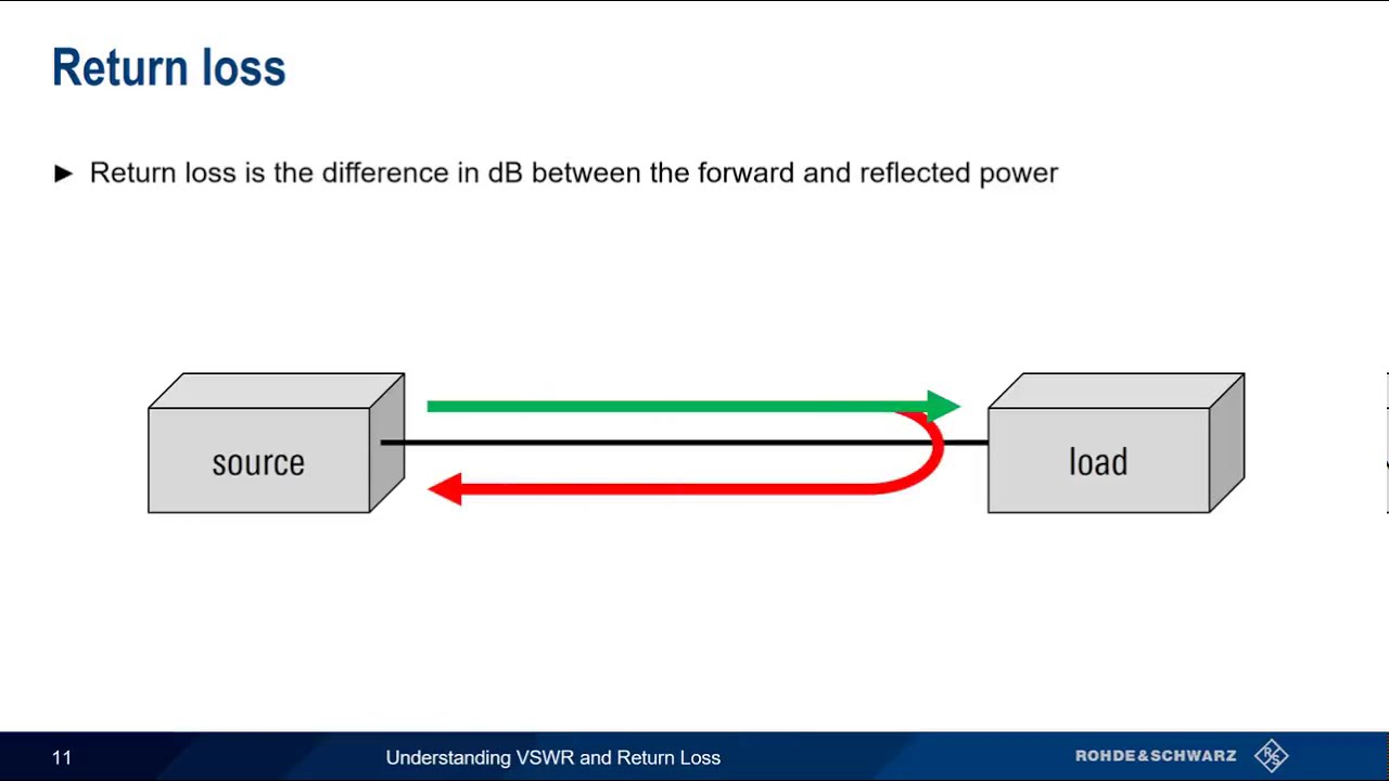
Image on Return Loss taken from This Video
Having return loss is good. You want very little of your signal reflected back to the source, so you want high reflected loss.
Return loss is caused by impedance mismatch. Your radio is designed for 50 ohms. The coax should be exactly 50 ohms, but design effects and other frequency-dependent effects may change that impedance. Lastly, your antenna may not necessarily be 50 ohms. At any of these points, you may experience loss due to impedance mismatch.
The ideal return loss is infinite. It can be neatly described as the ratio of incident power to reflected power, meaning how much power is delivered to the system versus how much is returned. Often return loss will appear as negative - this is just a convention.
$\text{Return Loss} = (-) 10 \log{\frac{P_i}{P_r}}$
Insertion Loss
Return loss describes errors with reflected waves. But some losses are unpreventable. Insertion Loss refers to power dissapated in the circuit itself. This is due to ohmic losses, heat, and the actual design. This is the length loss for coaxial cable and antenna wire - something we can’t work around.
It is described as the ratio between transmitted and received power. It should be as low as possible.
$\text{Insertion Loss} = (-) 10 \log{\frac{P_t}{P_r}} $
These two losses don’t describe two halves of a whole, but feature the major points in microwave theory.
S-parameters
S-parameters describe how signals behave in a “black-box” environment. Factually we identify an input signal (the radio) and observe an output signal (power at the antenna in this case, but generally radiated power). The s-parameters describe what happens in between. These parameters appear in a matrix (called the S-matrix).

Visual tool from wikipedia
There’s a lot of behind the scenes math, but the important points are:
- $S_{11}$ is the input Return Loss
- $S_{11}$ is the output Return Loss
- $S_{21}$ is the Insertion Loss
- $S_{12}$ is the reverse isolation, not often used
Remember the black-box diagram. There are inputs on either side of the system.
Measuring S-Parameters
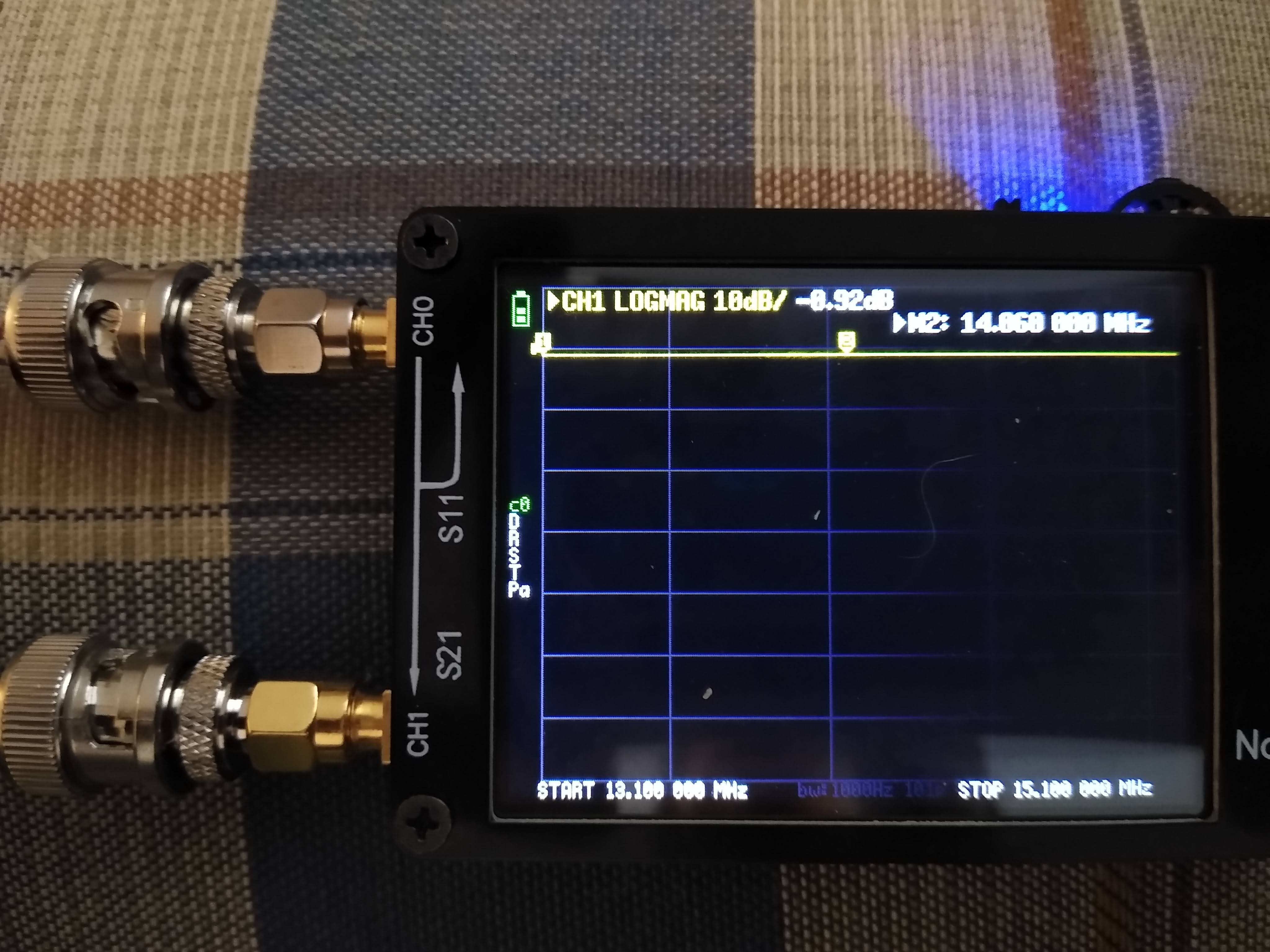
I just crimped two BNC connectors onto about 40 feet of RG-174. To look at the parameters, I used the nanoVNA as a small but powerful tool in measuring S-parameters. It’s more than just VSWR!
Remember I said input/output Return Loss is S11/S22. I chose an arbitary end of my coax as the input and the other as the output. S21 is the insertion loss, which does not require a side. The coax is plugged into both ports.
Since I usd BC, I had to use a BNC-SMA adapter. The return loss for both of these performed well (terminated in 50 Ohm load, got -43 dB). I got the following table for the cable at 14 MHz:
| S-parameter | Value (dB) | Ideal (dB) |
|---|---|---|
| S11 | -34.5 | -50 |
| S22 | -34.7 | -50 |
| S12 | -0.92 | 0 |
To measure, I perfomed the following steps:
- Connect both BNC-SMA connectors to the VNA
- Connect the cable to both connectors
- Measure “LogMag” on CH0. I’m assuming here that the unused CH1 port terminates at 50 Ohms. This gives S11.
- Switch sides of the cable and remeasure for S22.
- Switch “channel” to CH1, and measure S21.
So I get about 1 dB of loss for my entire cable. Not terrible.
Measuring S21 with the NanoVNA
Overall, this is a good gut-check that my cable will work. It isn’t a physical test, but a validation that I crimped it correctly.
Coax: Wavelength Dependence
This resource gives great advice on the practical side of coax.
Essentially, the HF signal traveling through the coax has properties, namely its wavelength. This wavelength must coincide with the length of the transmission line to ensure maximum current is delivered at the terminus of the cable.
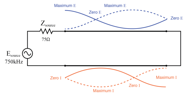
Standing waves in transmission line. Replace 75 Ohms with 50 Ohms, and the power with about 5W.
If there’s reflection from S11 or S21, waves will reflect back to the source causing destructive interference. If the coax length is not resonant, meaning it is a precise fraction of the wavelength, then standing waves will also be produced. Therefore the coax must be a certain length coincident with frequency.
Input Impedance
A better explanation uses input impedance. The impedance of the system will change depending on the coax length source
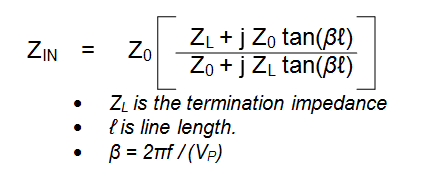
Even though the effect may be miniscule, it is important to match the length carefully with the load. This means at 14.05 MHz, my impedance is still 50 Ohms, but if the load impedance was changed (considering how a dipole has characeristic impedance of 70 ohms), then my input impedance is 67.2629 + 9.2925i Ohms.
Transmission-Line Loss and Velocity Factor
As I said before, S21 is the insertion loss due to natural effects in the cable. The length can actually be measured from the S-parameters using the nanoVNA and open software.
Velocity Factor refers to the actual speed at which EM waves travel through the cable. We saw on the datasheet that RG-174 is close to 0.66%. Using this speed and measuring delay, the length can be estimated.
This guide has a step-by-step tutorial, as does this video I’ve measured and attached my results here.

Estimated Length (9.662m) and Associated Graph
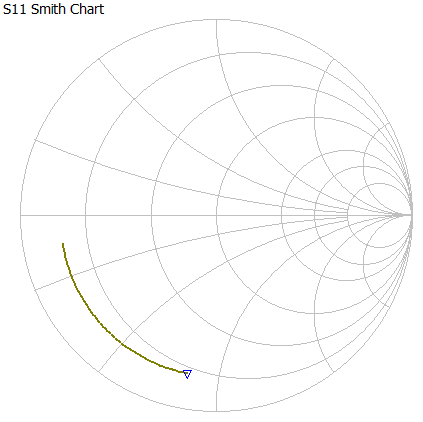
Smith Chart from the software
Recommendation / Conclusion
To sum it up, we learned:
- A dipole is a must, but a center conductor requires coaxial cable.
- Coax has different intrinsic losses based on its type
- Coax has S11 (return loss) due to reflections or poor construction
- Coax has S21 (insertion loss) due to length
- The length of a cable must depend on the signal transmitted, or else standing waves will be produced
So what to do with this information?
- I picked RG-174 as the “ultimate” cable for this antenna
- Measure the S11 and S21 to verify the coax is within acceptable values
- Use shorter sections of coax to limit loss
- Try to make the coax length resonant with the wavelength, but most important make the antenna height resonant
Combined with the characteristic impedance of a dipole the transmission line will have an interesting effect on impedance. More to follow on a final methodology for creating this system.
Hope you enjoyed this in-depth look at coxial cable. Note I referenced largely theory and academic resources, not amateur radio. You want to go with the math, not the superstition.
-N2WU