Introduction
As you’ve read from my several (4 1/2) SOTA outings, I very much enjoy the challenge of remote field-expedient NVIS antennas. Although I’ve been at elevations reaching 11,000 feet, I have never had much success on the bands - I tune to an SWR of about 1.6:1 and struggle to reach California with 10 watts CW. I sought something better - The End-All SOTA Dipole. In this post I will detail my literature review, materials needed, construction, and tuning to build your very own (patent-pending) N2WU SOTA dipole!
Past Antennas
The “Linked Doublet”
My former antennas as you remember are the QRPGuys Half-wave Endfed (linked) and my own personal attempt at a dipole - the “linked doublet”. Words do not do her justice - see for yourself:
 My trusty steed. May she rest in peace.
In the simplest terms possible (and please don’t laugh), the linked doublet is about 30ft of 450 Ohm ladderline connected to roughly-estimated resonant 10,20, and 40m linked dipole lengths in a vee configuration fed to the balanced input on my tuner.
Let me explain why this is a bad idea - theory curteousy of the brilliant Rex KE6MT. Doublets rely on a velocity factor - while ground travels on one ladderline, the signal travels on the other. Doublet’s velocity factor is influenced by frequency - LL lengths like 30ft are terrible as proven here.
Not only would my ladderline have to be linked in itself, but I chose the worst length for a single length of ladderline. No wonder I barely got Nevada…
So the doublet sucked. But a centerfed dipole places the highest amount of current near the center which would theoretically get your signal out the most.
QRPGuys Half-Wave Linked End-Fed
My other antenna, and my workhorse once I found the glaring issue with my doublet, was the QRPGuys end-fed. It said no-tune, but I was the one who cut the lengths. Therefore I had to tune it. I cut the 40m half-wave in half again to make a 20m element that linked to 40m. It performed pretty well at the top of a mountain getting me as far as San Francisco and Texas.
Tim N6CC had great choice words for the end-fed antenna:
End-fed wires? They must be great; everyone is selling them! Meh.
The generic End Fed Wire and the End Fed Half Wave (EFHW) is a special case of those. They are all the rage these days, and as with any conductor up in the air, they will produce contacts.
I knew I could do better than burying my highest concentration of current in the ground. At last, the N2WU SOTA Dipole!
Preparation
I spent a lot of time researching how to craft a simple dipole. They all agreed (erroneously) on one point:

Make no mistake, this is a challenging beginner project. But the learning curve is inverse - if you do it once, the second time is much easier.
Literature Review
Much of my design comes from this video. I googled “Center-fed dipole insulator” for construction ideas on the center elements and insulators. Of course, the best resources for linked dipoles can be found on SOTABeams, VK5LA, and CQHQ. They all give the same advice - keep it light, use a 1:1 choke, and get creative with the linked insulators. Armed with this approximate knowledge, I took to the garage to scrounge for materials.
Materials needed
I needed the following materials. I am not associated with any amazon links.
- 75ft Insulated Wire. I used 24gauge teflon-coated copper stranded wire.
- 4 sets of 2mm Bullet Connectors
- 3 inches of 1.5” diam. PVC pipe
- Zip ties (20 to be safe) - the smaller, the better
- BNC Chassis Mounts
- 1’ x 1/2’ Polycarbonate Sheet - $2 at a hardware store
- FT 140-43 Toroid
- 4ft of 18-22 gauge speaker wire (two separate conductors) OR RG-58
- Shrink Tubing
- 20-30ft of RG-58 with BNC connectors
- Female BNC - Male SMA adapter for the NanoVNA
Tools Needed
- Drill with 1cm-2cm drill diameter bits
- Hacksaw/Table Saw for cutting PVC and polycarbonate
- Wire Strippers / Cutters
- Soldering Iron / Solder
- Electrical Tape
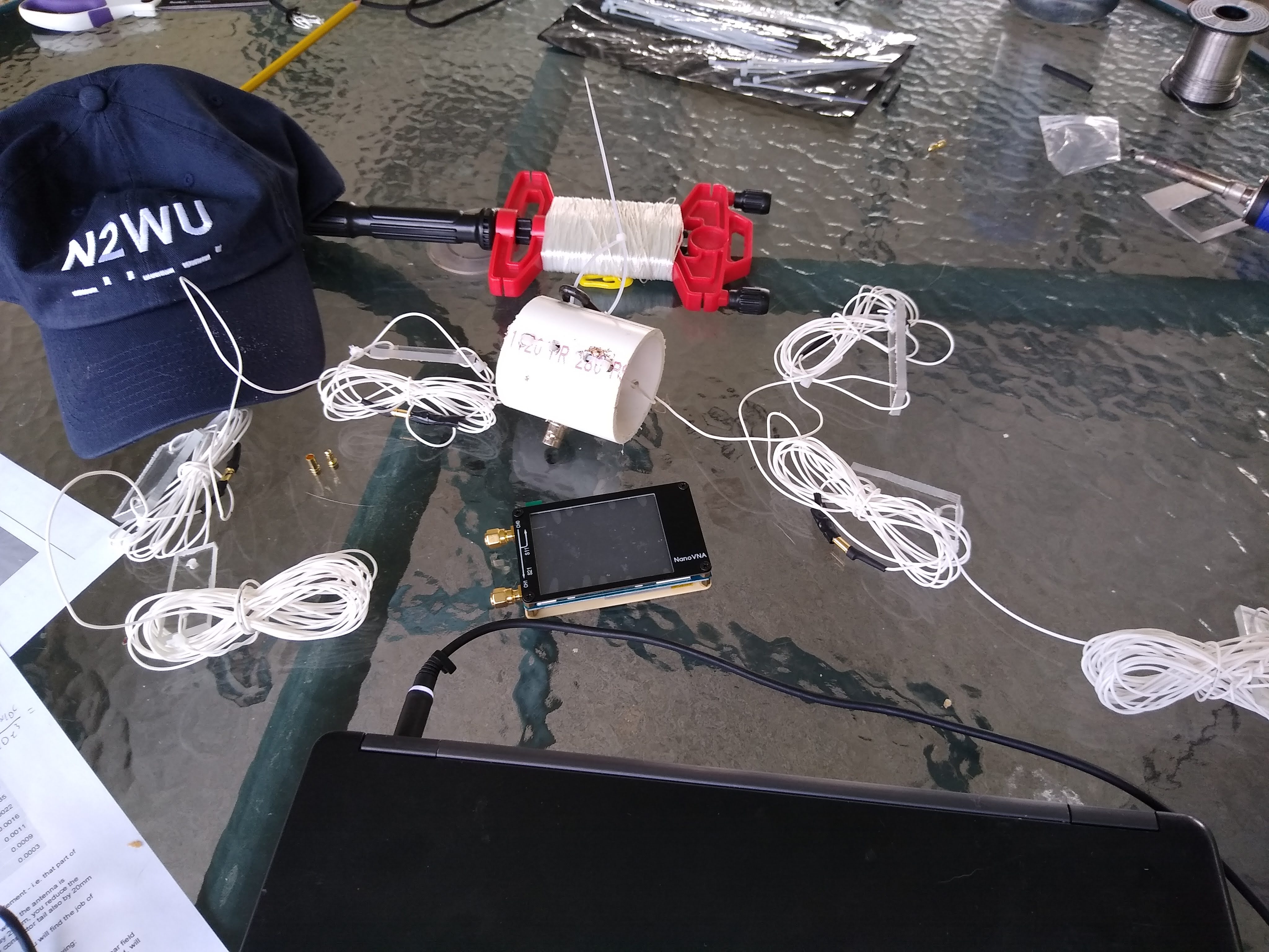
- Your favorite Antenna Analyzer - mine is the NanoVNA.
Cherries on top
- Hot glue gun
- Nylon rope
- A kite winder This is now in my SOTA kit.
Construction
This was a long process. Measure twice, cut once. Or, measure once and get on with it already.
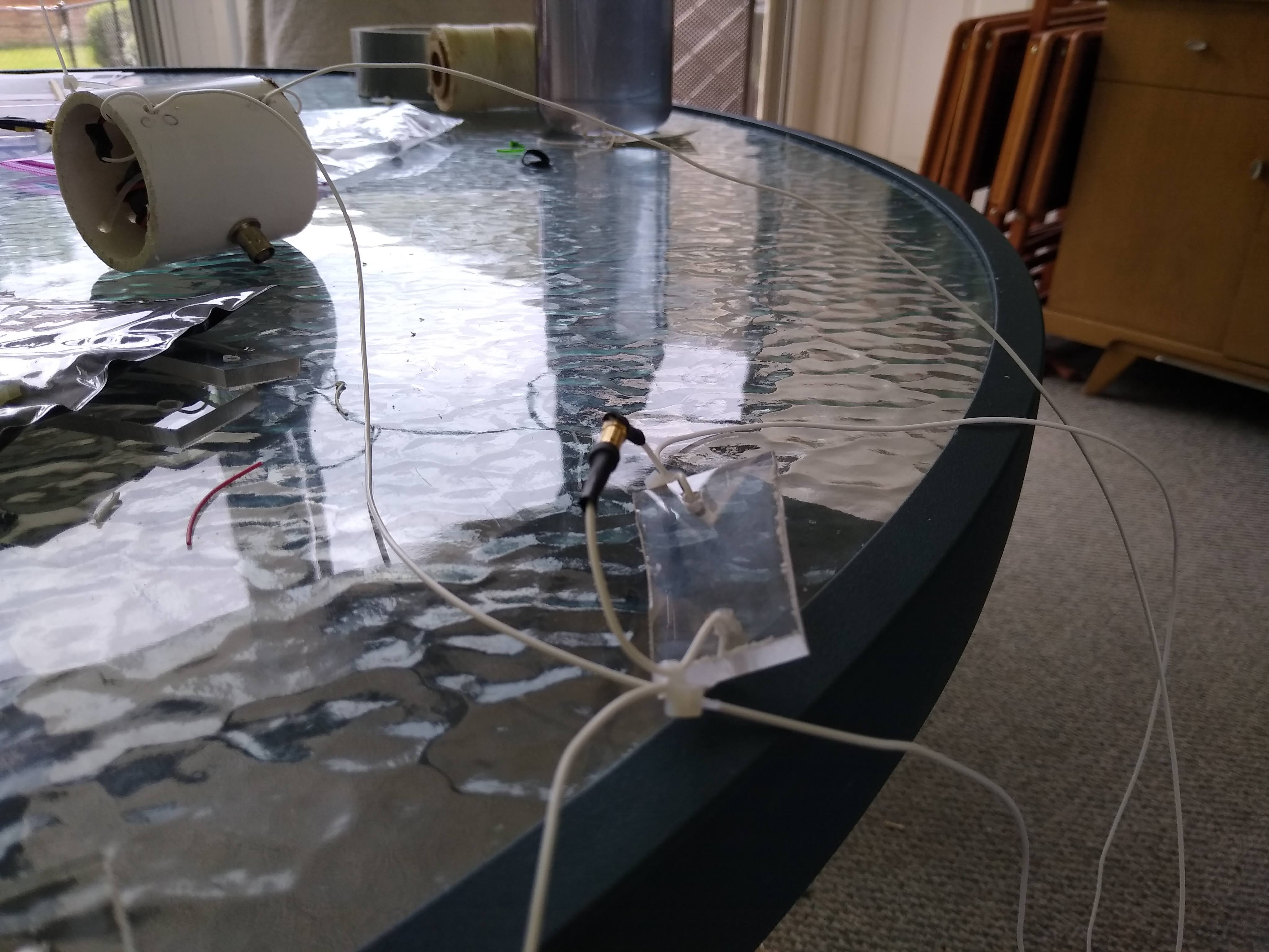
Center Element
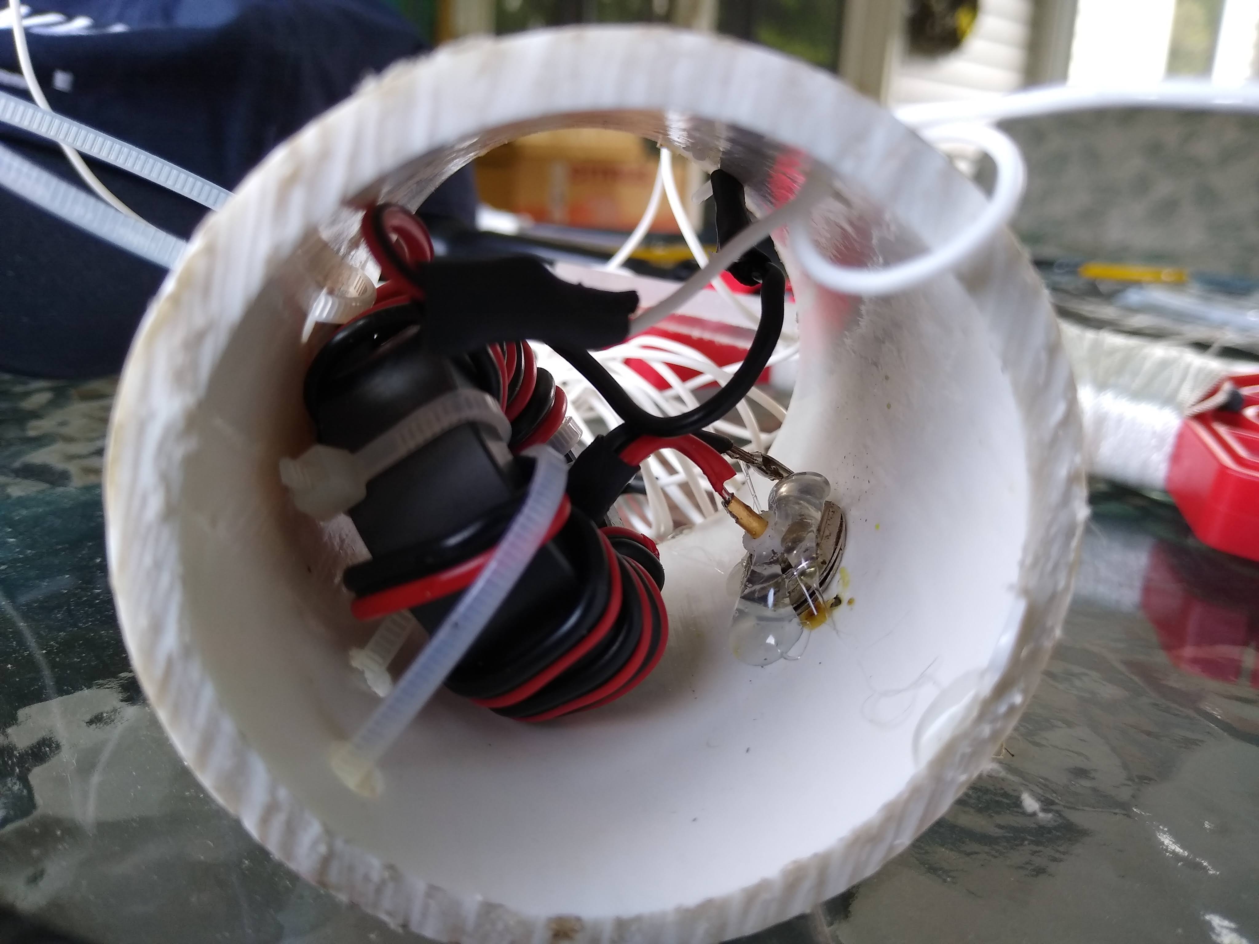 Closeup of my Center Element
I have seen a lot of designs that use 3D printing or some sort of mount for the BNC chassis. Had I a 3D printer, I would have gone with this method. However, I was armed with only my wits and the trash in the garage. Googling “Center Dipole Element” came up with several PVC designs so that’s exactly what I used. Here’s a breakdown of the steps used to make the center element:
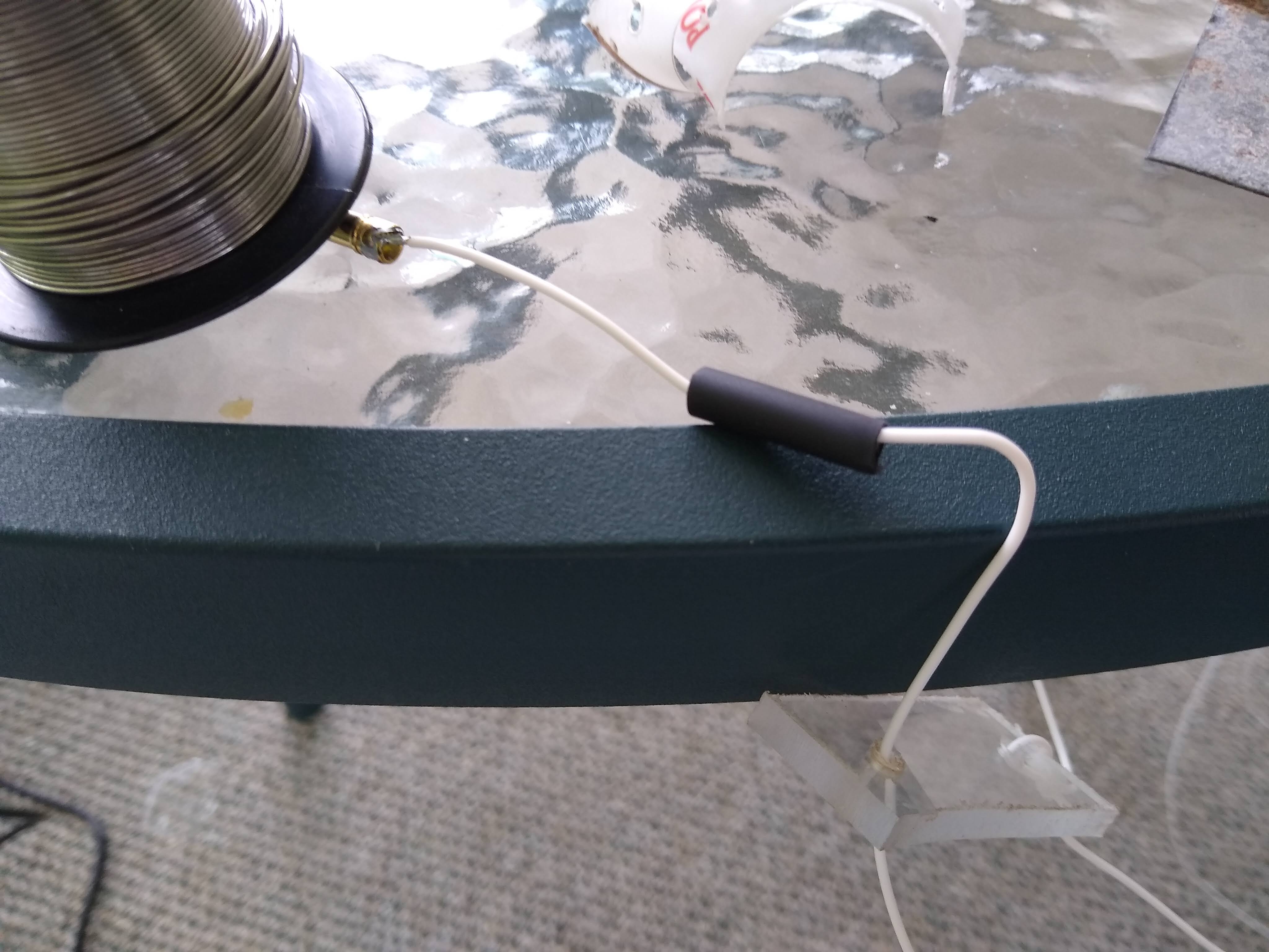
- Wind 1:1 choke
- Cut and Drill PVC Pipe
- Install BNC Mount
- Install Balun / Solder
- Install wire lengths
For the 1:1 choke, reference this video. You won’t need a lot of extra speaker wire lengths since everything is jam=packed inside the pipe.
The PVC pipe has the following holes drilled:
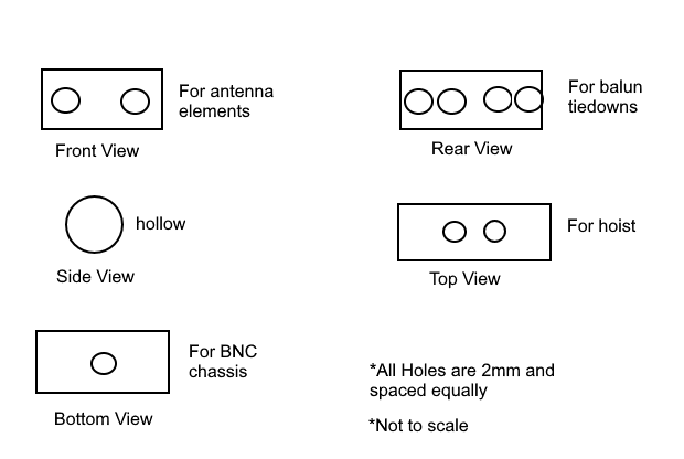 Drilling Chart
Additionally, you can secure all elements within the center insulator with hot glue and zip ties. PVC endcaps could even help waterproof the design.
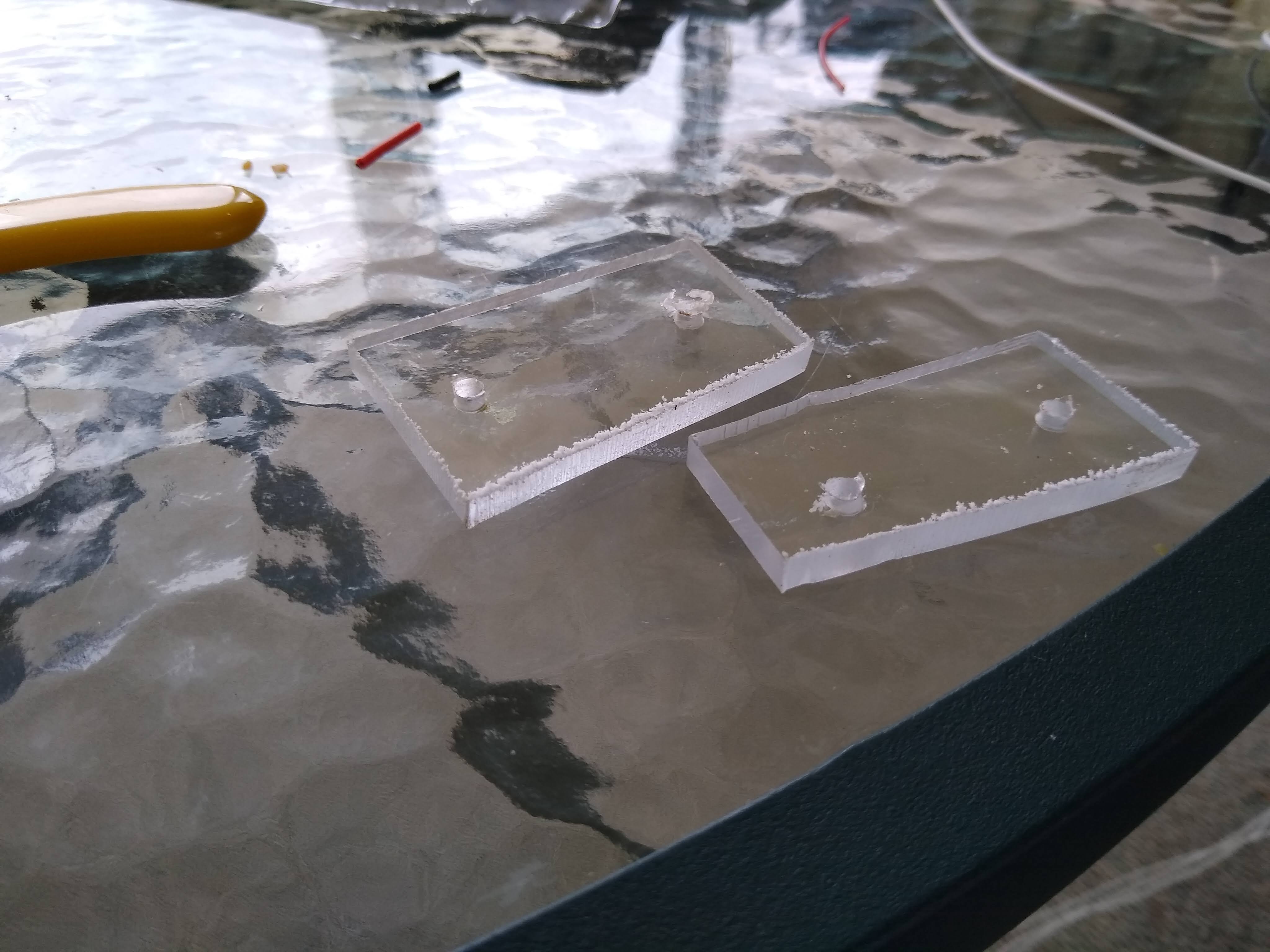
Linked Insulators
The linked insulators are literally just scrap. Tim N6CC has an awesome design on some of his portable military operations:
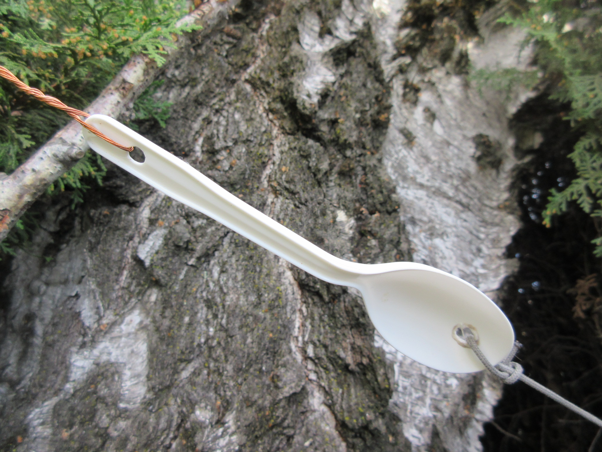
All I use are 1” x 2” polycarbonate sections with 2x 2mm holes drilled in:
My linked connectors are very useful bullet connectors designed for motors and batteries. Stress is alleviated (in the antenna, not in me) with zip ties. Shrink tubing minimizes RF exposure and waterproofs. When I install the antenna elements, I have to follow a certain procedure to make sure I don’t forget anything.
- Thread the wire through the fiberglass
- Slide heat shrink onto wire and move about 2’ down the wire
- Strip and solder bullet connector
- Wait, then apply heat shrink
- Add zip tie
My job lends itself to being really good at following directions, so this is the most helpful way I could communicate.
Wire
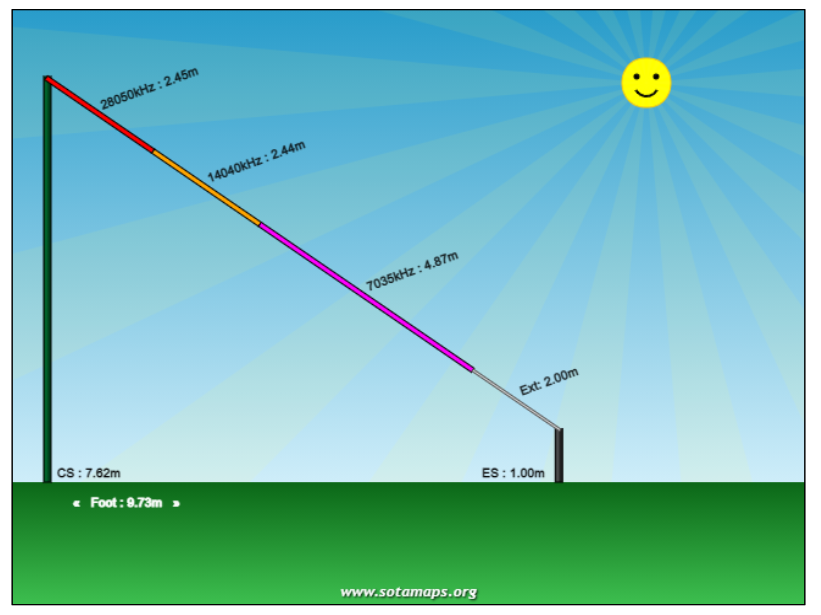
I used the SOTA Extras Dipole Calculator for all my lengths. I chose 10,20, and 40m CW. When I measured, I marked at the exact measurement and gave myself an extra foot when cutting. On tuning I still started at the exact length with the extra folded over.
Testing
Here’s where you test your mettle (and metal!). This can be an incredibly painful or a pain-free process depending on the HF gods.
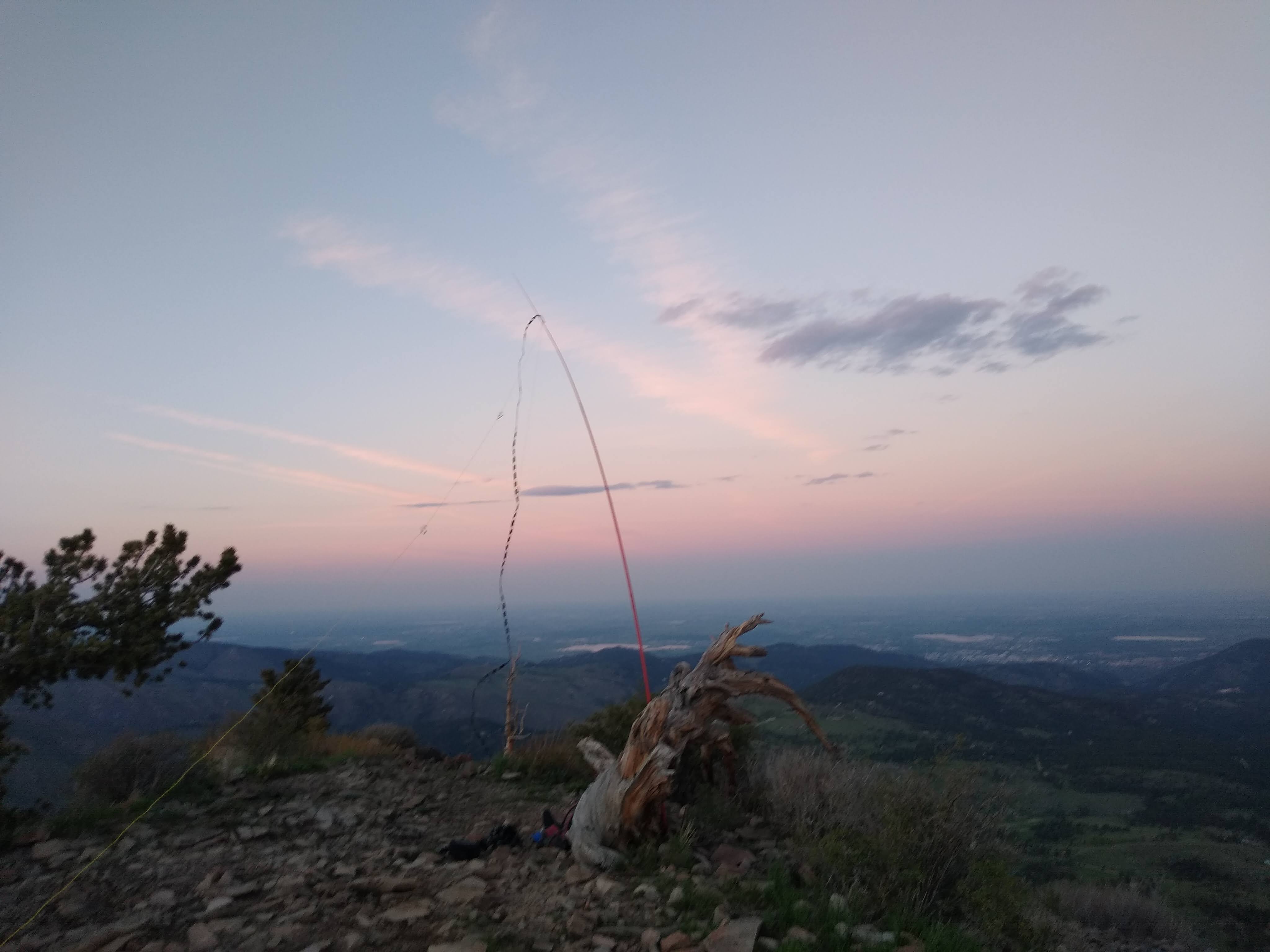
Field Deployment
First, I was digging around for some rope and found 20lb-rated Kite String with a winder. This little guy made my day. Here’s how I deployed the antenna each time:
- Affix tossable weight (fishing lead, rock) to nylon string
- Chuck into tree, preferably 30ft tall
- Eyeball center element location on string when weight touches ground
- Tie slipknot in kite string
- Affix center insulator to string via carabiner
- Plug in feedline
- Hoist
- Secure radiating elements
The smaller weight, the less likely you are to get snagged irretrievably on branches. Tim N6CC uses lead fishing weights, and I agree - the smaller and denser, the better.
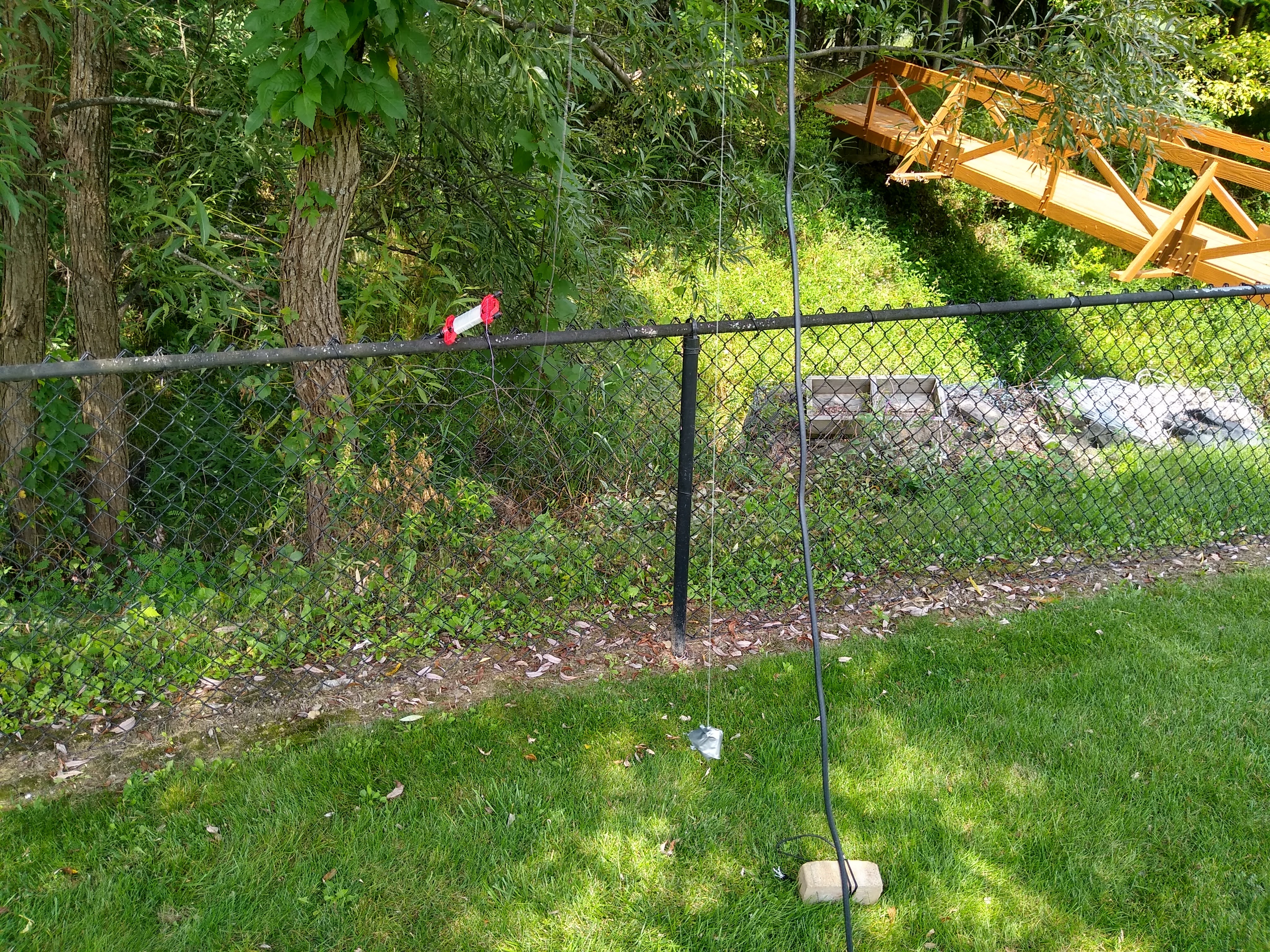 Picture of Kite Winder, rock, and extra brick
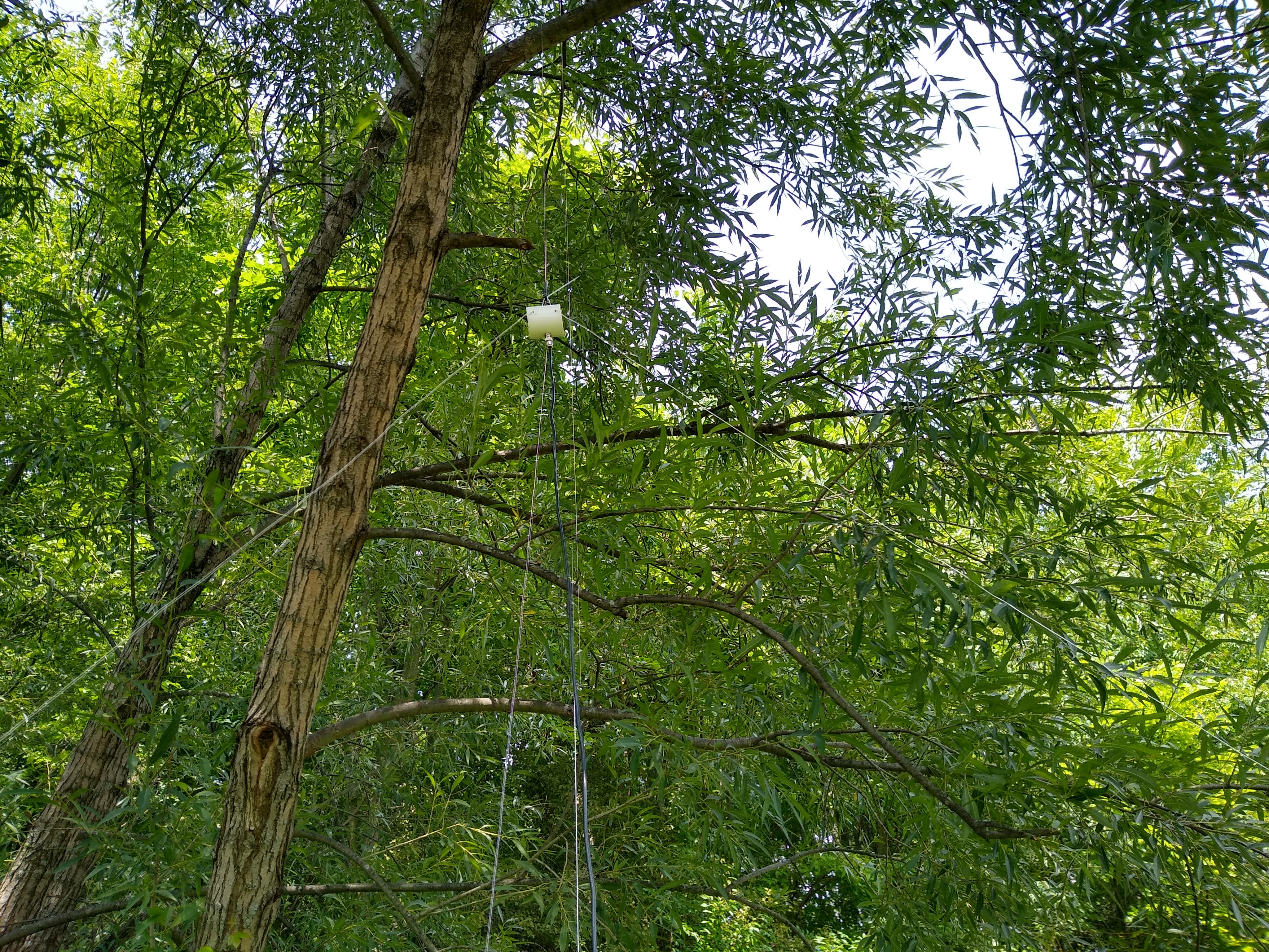 Center Element hoisted
Tuning
Tuning is a careful art, of sorts.
 Expert Elmer Bob Ross gives some advice
Some general tips for tuning:
- Keep both elements identical in length
- Fold instead of cutting
- Never do anything permanent while the antenna is in the air
I folded my lengths instead of cutting. Here’s how I tuned:
- Begin at the calculated length with 12” of fold-over taped to the antenna itself
- Using the NanoVNA, measure SWR for (center - 1 MHz) to (center + 1 MHz). For example, 13 to 16 MHz. You should be pretty close already
- Make calculated adjustments to both antenna elements at the same time without cutting
- Find your final measurement and add 2” for the linked insulator portion
That’s it! It is a lot of back-and-forth, but your center element doesn’t move, just the guy ropes and your end radiators. Also to save time, store your calibration settings for the NanoVNA.
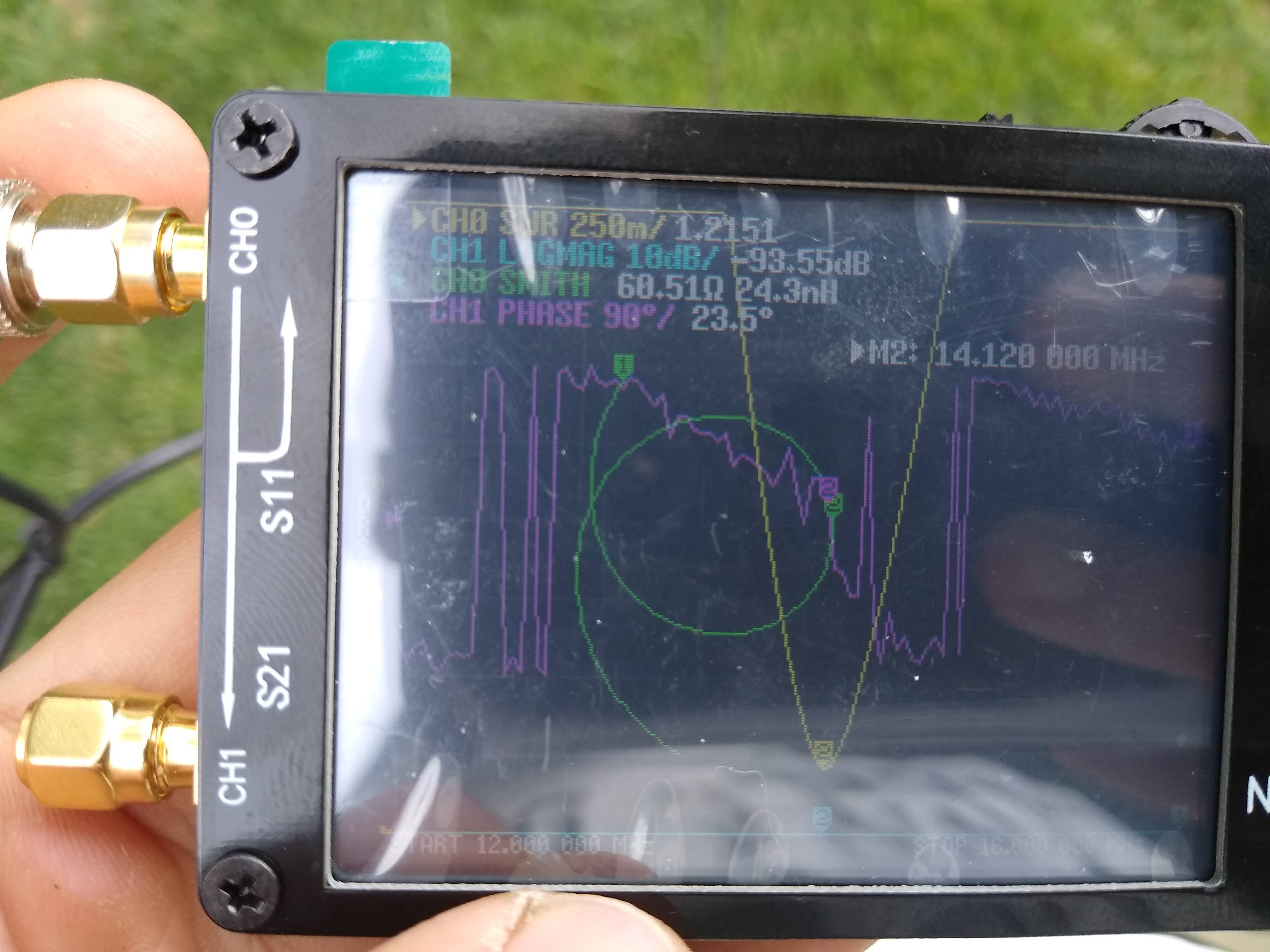 NanoVNA Display for 20M
Final Thoughts
After all required tuning, I stuck a last pair of insulators on the end to tie down with guy wires. To coil the rope, I make figure-8s with my index and thumb similar to this method.
Overall I am glad to finally have a working solution for the summits. Watch out, 1-pointers of the Greater Catskills Range!
I had a great time making this antenna. Stay tuned for W2KGY’s first annual SOTA activation this fall!