Introduction
Over my time at Boulder this summer, I was able to do some mathematical modeling and signal analysis using MATLAB and python. Further, I started on some efforts for remote control of a RS232-enabled rig. Continue reading for my code breakdown! It is all available on my github.
 Where the magic happens!
MATLAB Bit Error Rate Comparison
Background
First, I made a bit-error rate comparison code for a graduate program at Boulder. It was used to analyze generated and received bits and give an in-depth error analysis. The code follows the NASA Comms procedure found here.
The first thing I do is analyze the header of each packet separate from the payload.
Header Analysis
To extract the timestamp from 50 packets and store them in a column, I use the Data Acquisition Toolbox for simple binary:
for n=1:50

decTime(n,:) = bi2de(TimePortion(n,:));

end
Packet Analysis
To actually find the BER, I do some simple xors between trusted and generated data. Unless I add gaussian noise, I should get a BER of 0% every time. The following code calculates the number of bit errors:
BitErrors = xor(TrustedData,ErrorData);
BitErrorNum = zeros(1,psize);
for m=1:psize
    %BitErrors(m,:) = xor(TrustedData(m,:),ErrorData(m,:));
    for k=1:length(BitErrors(m,:))
        if BitErrors(m,k) == 1
            BitErrorNum(m) = BitErrorNum(m) + 1;
        end
    end
end
The next portion cuts each group of 8 bits into bytes using a modulus function, and finds the individual byte errors. It probably can be optimized:
NumBytes = length(TrustedData(1,:))/8; %Should be 28
ByteErrorVector = zeros(psize,NumBytes);
ByteStarts = zeros(1,NumBytes);
%Find ByteStarts Matrix
ByteCounter = 1;
TempErrorVector = zeros(1,8);
ByteErrorSum = zeros(1,psize);
for g=1:length(BitErrors)
    if mod(g,8) == 0 && g ~= length(TrustedData(1,:))
        %ByteStarts(ByteCounter) = g+1;
        TempErrorVector = xor(TrustedData(m,g+1:g+8),ErrorData(m,g+1:g+8));
        TempErrorSum = 0;
        %calculate bit errors
        for b=1:8
            if TempErrorVector(b) == 1
                TempErrorSum = TempErrorSum + 1;
            end
        end
        ByteErrorVector(m,ByteCounter) = TempErrorSum;

        ByteCounter = ByteCounter + 1;
    end
    for c=1:length(ByteErrorVector(1,:))
    if  ByteErrorVector(m,c) == 1
        ByteErrorSum(m) = ByteErrorSum(m) + 1;
    end
    end
end
CSV
I port each of the BER calculatons into a CSV for easier viewing as well. The first snippet works for each section of code - just check that your data fields fit the type.
FinalCell(:,4) = cellstr(num2str(ByteErrorSum.'));

%Add labels on top row
FinalCell_Label = cell(51,4);
FinalCell_Label(1,:) = {'Sequence Number','TimeStamp','Bit Errors','Byte Errors'};
FinalCell_Label(2:51,:) = FinalCell;

CSV_Table = cell2table(FinalCell_Label);
writetable(CSV_Table, 'CQC_Error_Checking.csv');
Python Remote Temperature Control
Next, I attempted to control a RS232-enabled device for remote commands over python scripts. I used a library called minimalmodbus and the command protocol available here.
Author’s Note: I never got this quite to work. Read with a pinch of salt.
 Temperature Rig in Question
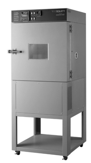
Temperature Control Rig:
The rig is the TestEquity Model 115A Temperature Chamber with F4 Controller - very important for our uses. It took register commands to read and write registers. Brushing up on my assembly skills helped. I relied mainly on the temperature chamber’s document, but I also dove into the F4 procedure available here.
Code
First, I discover the port. I was using a windows machine and had a fair amount of headache trying to rediscover the named USB port. I cheated and referenced the port statically - in future versions I will try to reference it by a serial number or named aspect of the RTU controller.
serialPort = 'COM16'


# Define the instrument and list parammeters
instrument = minimalmodbus.Instrument(serialPort, 1)  # port name, slave address (in decimal)
instrument.serial.port                     # this is the serial port name
instrument.serial.baudrate = 9600         # Baud
instrument.serial.bytesize = 8
instrument.serial.parity   = serial.PARITY_NONE
instrument.serial.stopbits = 1
instrument.serial.timeout  = 0.05
instrument.close_port_after_each_call = True # necessary for windows
Next, I actually access the registers to read and write commands. Following from page 4-14 on the technical specification:
## Read temperature (PV = ProcessValue) ##
temperature = instrument.read_register(100, 1)  # Registernumber, number of decimals
print("Temperature is", temperature, "Degrees")

## Change static temperature setpoint (SP) ##
NEW_TEMPERATURE = 1000
instrument.write_register(300, NEW_TEMPERATURE, 1)  # Registernumber, value, number of decimals for storage
print("Temperature Set to", NEW_TEMPERATURE/10,"Degrees")
temperature = instrument.read_register(201, 1)  # Registernumber, number of decimals
print("Temperature is", temperature, "Degrees")
Here’s where it gets tricky. I never get readable numbers when I read the “temperature” variable. I’ll have to look more into this.
GNURadio Viterbi Decoding Algorithm
The last (unsuccessful) project I undertook was decoding convolutionally-encoded packets via gnuradio. I ran into the usual GNURadio headaches - outdated versions and legacy blocks!
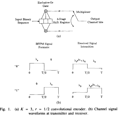
Theory
This Video is a great resource on how to visualize encoding and decoding. Here’s a brief textbook diagram for encoding:
Essentially, my project has the following steps:
- Generate data bits
- Encode bits
- Modulate packets
- Demodulate packets
- Decode bits
- Compare data bits
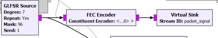
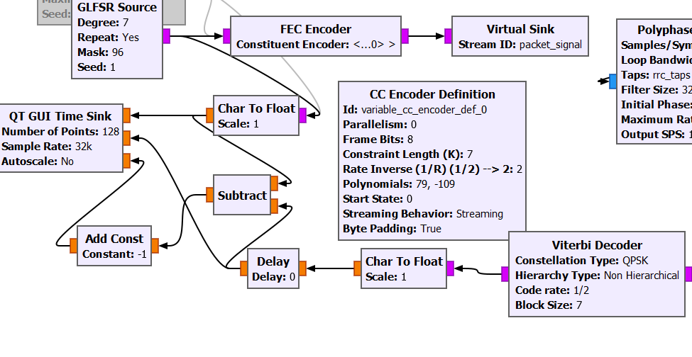
Encoding and bit generating
I used my code from a previous BPSK post to try and generate packets. It uses a tagged stream and CC Encoder blocks to encode. It also uses the “tagged stream” block and ecosystem to format into packets - I’ve tried methods with and without headers and headers give less BER.
The GFSLR source gives a constant, periodic output I can compare to easily.
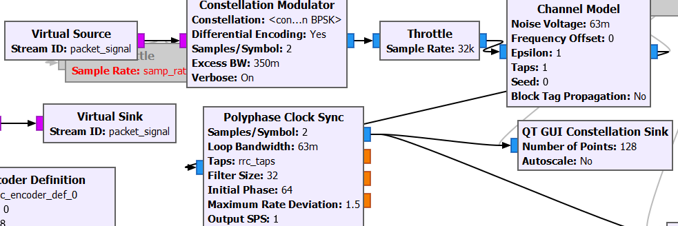
Modulating
I modulate using my normal habits - a constellation modulator with channel model. I put the throttle block in the middle since I get most of my errors on constellation visualizing. The program always seems to run for about 15 seconds, then hangs. It isn’t a hardware limitation but something else I can’t wrap my head around.
Demodulating
I used just a binary slicer to demodulate from integers to bits. This doesn’t appear wrong, but doesn’t ever appear correct either. More work will be done on what signal is actually being received at this point.
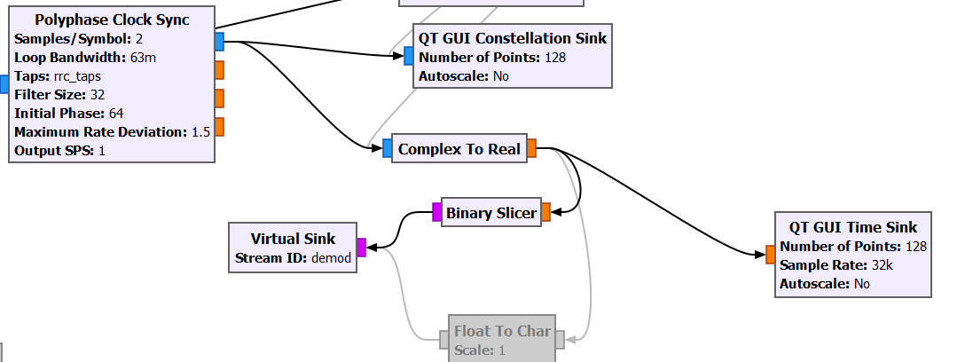
Decoding
Finally, I tried several different methods to decode and display the bits. The CC Decoder blocks are legacy with little documentation - I can’t actually tell if they work. Further, other Viterbi blocks come from DATV and have nonstandard parameters. This output has the two data streams on the same graph where they can be analyzed for consistency.
Possible Fixes
I have searched far and wide for a fix, but until more documentation and support comes for the CC Decoder block I can’t analyze much. Rumor says the GR_Satellites plugin has support for viterbi decoding. Additionally, the legacy Encode/Decode CCDS27 block has the same goal with a different input packet (original packets from a NASA Satellite!). I will watch the status of this via much smarter GNURadio operators.
Odds and Ends
Boulder was a great time with SOTA excursions, USIAP activations, triathlon training grounds, and college tours. I was able to meet up with several area hams from SOTA and my second passion, amateur ballooning! EOSS met with me several times to discuss ongoing projects.
Balloon Adventures
Edge Of Space Science (EOSS) met with me several times to discuss ongoing projects. While I won’t post about these until they are completed, you can see some work ongoing on github. I am most excited for a balloon ecosystem and TNC board, combining several years of my research!
Huge thanks again to all the researchers and hams who made my time at Boulder so incredible. Go Buffs!