After a few more summits, I’ve decided my SOTA getup needs serious work. The amateur radio community largely acts on instinct and legend, so I’d figure I actually do the math in creating an ultimate SOTA antenna.
Part 2 will cover one of the most unknown components of amateur radio - the balun. I’ll review its purpose, use, and feasibility in this SOTA setup.
Introduction (from previous)
I want you to close your eyes. Peek a little at a time to read if you have to or have someone read this part aloud. Eyes closed? Ok. Picture what comes to mind when I say “Ultimate SOTA Antenna.” What shape is it? Frequency? Transmit power? Really focus on the little things and especially what makes it better than your current QRP setup.
Open your eyes. Let’s compare the big picture:
Requirements for “The Ultimate SOTA Antenna”
Construction
- Lightweight without complicated guy lines or solid tubes (save a fiberglass mast)
- Sets up quickly and stays up - no fuss
- No snagging on trees or getting stuck between rocks
Performance
- Has ideal SWR without a tuner
- Continuous DX the moment it’s online
- Maximum radiation efficiency - current concentrated at the highest point
In all, you want a simple antenna that does its limited job very well. What does this antenna actually look like? I’m going to say a single-band, half-wavelength dipole.
Actually, I’ve decided to make it a dual-band design. More to follow later…
For more background to my approach, visit the first post in the series.
So, without further ado, the humble and mysterious balun.
Balun Definition and Theory
For starters, most of my information here is coming from Jerry Sevick’s (W2FMI) Understanding, Building, and Using Baluns and Ununs and Transmission Line Transformers, 4th Edition. I opted not to use the first google results for “Inverted Vee Balun” because 1. most of these are just hams showing off that they built a balun with no theory, measurements, or characterizable results, and 2. there’s no evidence or justification they truly need one.
In terms of good online sources, DX Engineering has a good in-depth look. I would remind you, dear reader, that DX Engineering would benefit from you buying their baluns and thus they encourage every technician, general, and amateur extra to use a balun.
Balun General Schematic
“Transmission Line Transformer”
Baluns transform impedances. Read more of Sevick’s books to understand this concept. They are not inductors or transformers transmitting energy by flux linkage or magnetic fields- baluns are highly efficient.
The Inverted Vee and 1:1 Balun
The Inveretd Vee is a specialized case of the half-wave dipole. It’s bent at a Vee angle, with dimensions anywhere 45-90 degrees.

Vee General Design
A dipole in free space has an impedance near 70 ohms. When placed over ground (half-wavelength) the impedance tends towards 50 ohms. A 50 ohm load and a 50 ohm coax cable means a 1:1 balun is desired to match impedances.
So what’s the point of the balun?
Many believe the balun reduces skin effect and/or stray current. For the inverted vee, it’s a little more specific according to Roy K3MK:
“Key uses for the 1:1 current-balun: a) is to marginalize the “inverted-L current” in the transmission-line feeding a dipole-antenna. This will prevent a radiating Feedline and prevent distorting the antenna’s radiation pattern.” “There will be some flux in the core but it’ll be minor due to the small current causing it. This problem is covered at length in the 2007 ARRL Antenna-Book. b) drive balanced antennas (e.g. dipole or Yagi) with equal currents.”
We are concerned specifically with inverted-L current. Described in length in Sevick ch. 7:
To copy from the source:
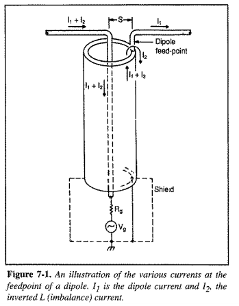
“Theoretically, a balanced antenna with a balanced feed would have a ground (zero potential) plane bisecting [the antenna]. However, because a coax-feed is unbalanced and the outer braid is also connected to ground at some point, an imbalance exists at the feedpoint giving rise to two antenna modes. One lies with I1, providing a dipole mode; the other lies with I2, providing an inverted L mode.”
L-mode current is based on the spacing between the center conductor and the shield:
“If the spacing, s, is increased, the imbalance at the feedpoint becomes greater-giving rise to more current on the outer braid and a larger imbalance of currents on the antenna’s arms.”
The spacing between these elements is on the order of millimeters compared to meters of wavelengths. Sevick concludes the separation is insignificant for wavelengths up to 20M, and that L-mode current is largely neglglible for HF operation. He relays a story about balun effectiveness on microwave frequencies, where he comes to the realization: The microwave antenna still used coaxial cable. This separation distance has a much larger effect on L-mode current than HF L-mode.
By this published definition, baluns seem unnecesary for dipoles due to the separation. What does practice, rather than theory, say?
On-The-Air Tests
Sevick did conduct a dollars-to-doughnuts balun and no balun test. His findings (ch. 7):
“I conducted experiments with Baluns on a 20-meter half-wave dipole at a height of 0.17 wavelengths, which gave a resonant impedance of 50 ohms. VSWR curves were compared under various conditions. When the coaxial cable was in the ground plane of the antenna (that is, perpendicular to the axis of the antenna), the VSWR curves were identical with or without a well-designed Balun-no matter where the outer braid was grounded. A significant difference was noted only when the coaxial cable was out of the ground plane. When the cable dropped down at a 45-degree angle under the dipole, a large change in the VSWR took place. This meant that the inverted L mode was appreciable.”
I claim in a SOTA setup, we will be operating directly under the mast. This means very little non-perpendicular coax deflection; therefore, a balun would be unnecessary in this situation.
Concluding:
“In general, the need for a Balun is not so critical with dipoles and inverted Vs (especially on 40, 80, and 160 meters) because the diameter of the coaxial cable connector at the feedpoint is much smaller than the wavelength.“
Not to cherry pick, but it does seem to be a popular opinion that a balun QRP dipole sounds the same as a non-balun.
Simulations
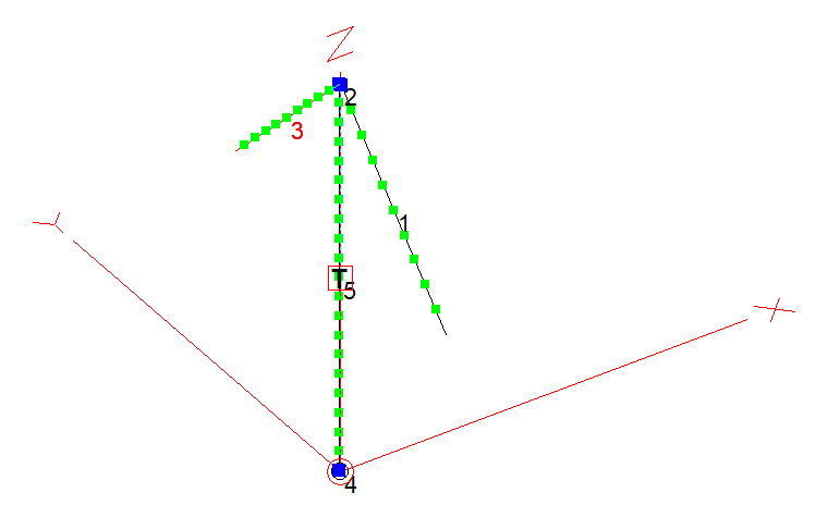
Asking amateurs the realizable effect of a 1:1 balun is often a fruitless question. It’s not necessary VSWR, even though it should reduce L-mode current and thus return loss down the coaxial cable. Maybe it could be directivity? So I loaded up EZNEC, built an inverted Vee with coax model, and tested with and without a balun.
I modeled the balun as a 50 $\Ohm$ series load between the coax shield and $V^-$ antenna side. This is explained in the eznec manual.
Here’s the antenna for 20M (14.06 MHz) at 9.1m above rocky ground:
SWR
Here’s its SWR without a balun:
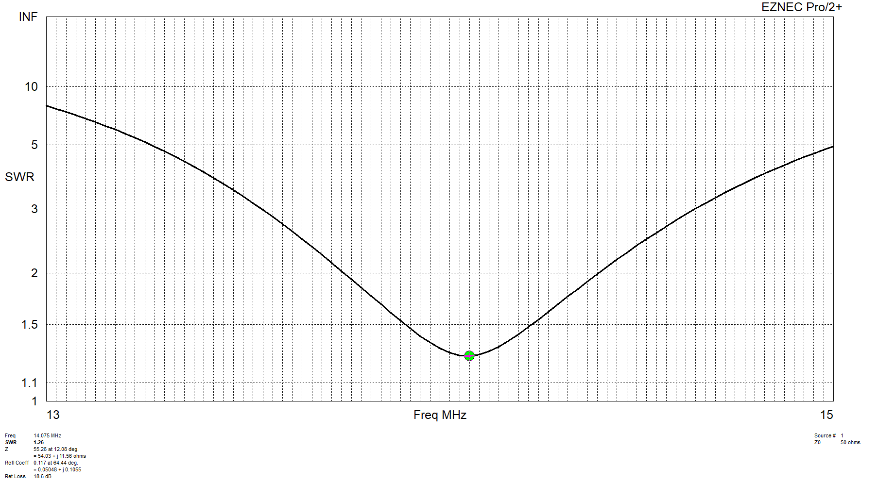
SWR with a balun:
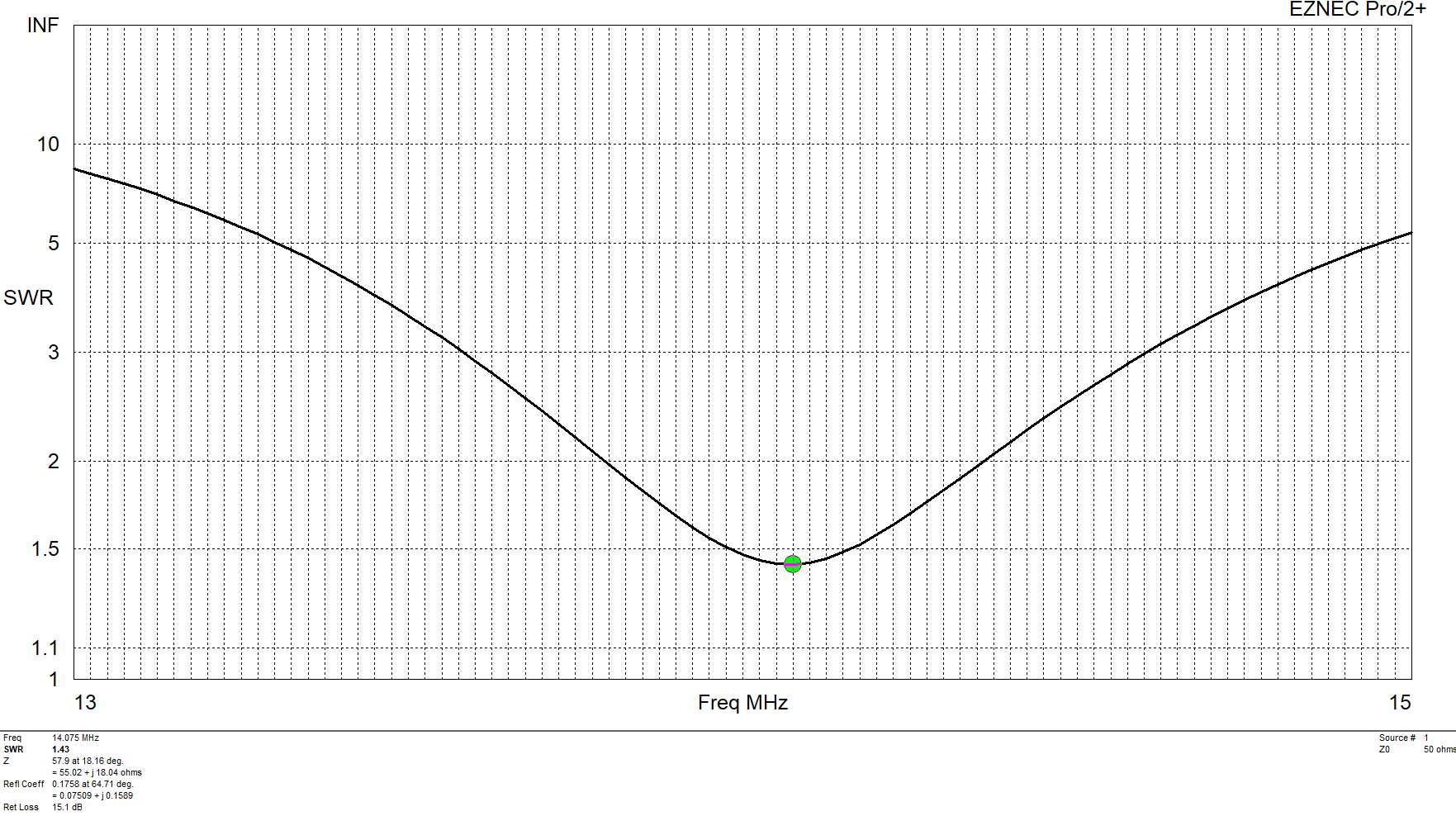
So the balun performs, if anything, worse than a non-balun design in VSWR.
Far-Field Plot
2-D Far Field Gain without a balun:
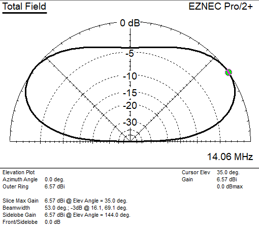
With a balun:
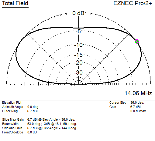
Surpsingly, this actually performs 0.13 dBi better with a balun than without.
Conclusion
In this brief lesson on the 1:1 current (guanella) balun for an Inverted Vee:
- A balun reduces L-mode current dependent on the distance between the center conductor and shield of a coax cable
- With a perpendicular coax cable and wavelengths up to 20M, this current is largely nonexistent
- Most simulations show no difference between balun and no-balun designs. My simulation shows worse VSWR and 0.13 dBi gain for a balun design.
As a result of these findings, I’ll opt to not install a balun. It has a greater room for error, as baluns are another point of failure in the link from radio to antenna. Ferrite cores may also break and add weight to the top of an antenna mast. Further, there would be a power-limiting tradeoff for selecting a lightweight core.
Hope you enjoyed and open for comments on this scintillating publication. -N2WU
More reading:
https://www.vk6ysf.com/balun_guanella_current_1-1.htm https://en.wikipedia.org/wiki/Dipole_antenna#Current_balun https://www.dxengineering.com/techarticles/balunsandfeedlinechokes/baluns-choosing-the-correct-balun https://www.eznec.com/Amateur/Articles/Baluns.pdf https://vu2nsb.com/antenna/wire-antennas/inverted-v-antenna-dipole/ https://www.ke6mt.us/wp-content/uploads/2020/08/fred-kt5x-antenna-ideas.pdf https://eznec.com/misc/EZNEC_Printable_Manual/7.0/EZW70_User_Manual.pdf