Following in the footsteps of my favorite neighborhood ham blog and good friend Steve K3GOG, I’ve decided to make a room-cleaning post detailing some odd work I got done to finish up the year. Little improvements in my SOTA setup yield larger gains out on the hills.
Background
If you see any serious SOTA Adventurer, they start to have pretty standardized equipment. Hams like Steve WG0AT, Adam K6ARK (who just started an awesome UL SOTA business), Rex KE6MT, George WS0TA, and Fred KT5X all have pretty much a standard “pack” for the lightest and most efficient operating. Rather than just buy my material off the well-known SOTABeams, a little engineering knowledge and cheap electronics parts make for a solid replacement.
Further, I like to have no-one to blame but myself. If I homebrew my own equipment, I can identify, fix, or improve upon failures.
If you look at November’s 2021 QST, you’ll even see David K3MA with a similar pack. So what’s in this pack anyway? Usually I’d argue:
- An Elecraft KX2 with internal battery and tuner (which I disagree)
- An End-fed Halfwave, or EFHW Antenna
- A mast for such antennas
- A lightweight CW key
Sure this setup is ultralight and compact, but it’s also ultra expensive. You’re paying for luxury. I’ve more or less got the same setup for a fraction of the cost:
- KX2 with custom case, external battery, and ZM-2 Tuner
- Homebrew EFHW
- Homebrew mast
- Homebrew key
I did pay a premium for the KX2, but with the Mountain Topper Radios scarce and how I lacked any rig, this was the way to go. Maybe someday I’ll build a case for the MT. Continue reading for the shoestring SOTA build guide.
Loose End 1: SOTA Antenna Mast
Inspiration
I previously had a mast for Windsocks that went about 30ft and stuck out 4 ft from my backpack. It was bulky but had a lot of character. I used it for my activation of W0C/FR-039, Estes Cone:
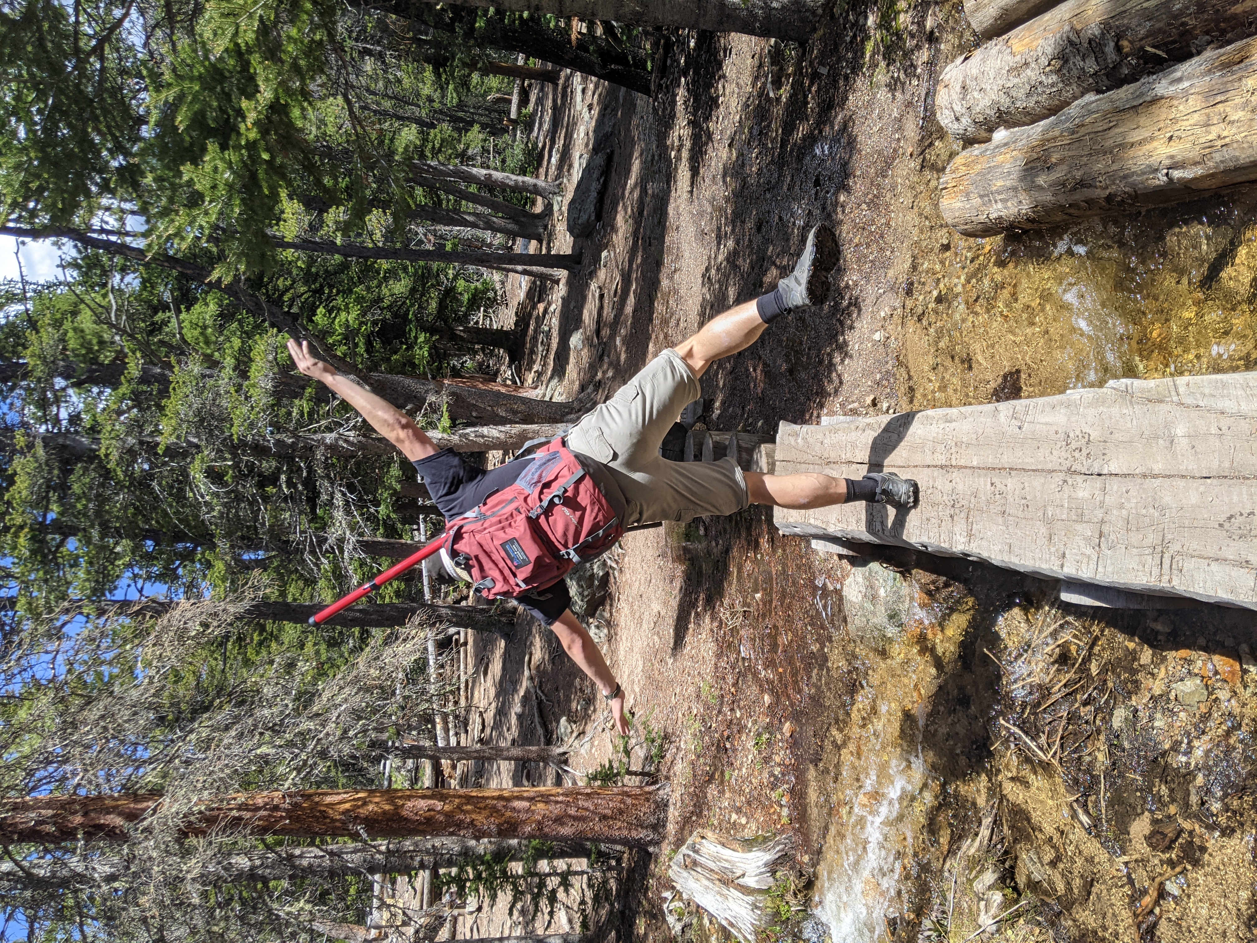
It worked nicely at the summit:
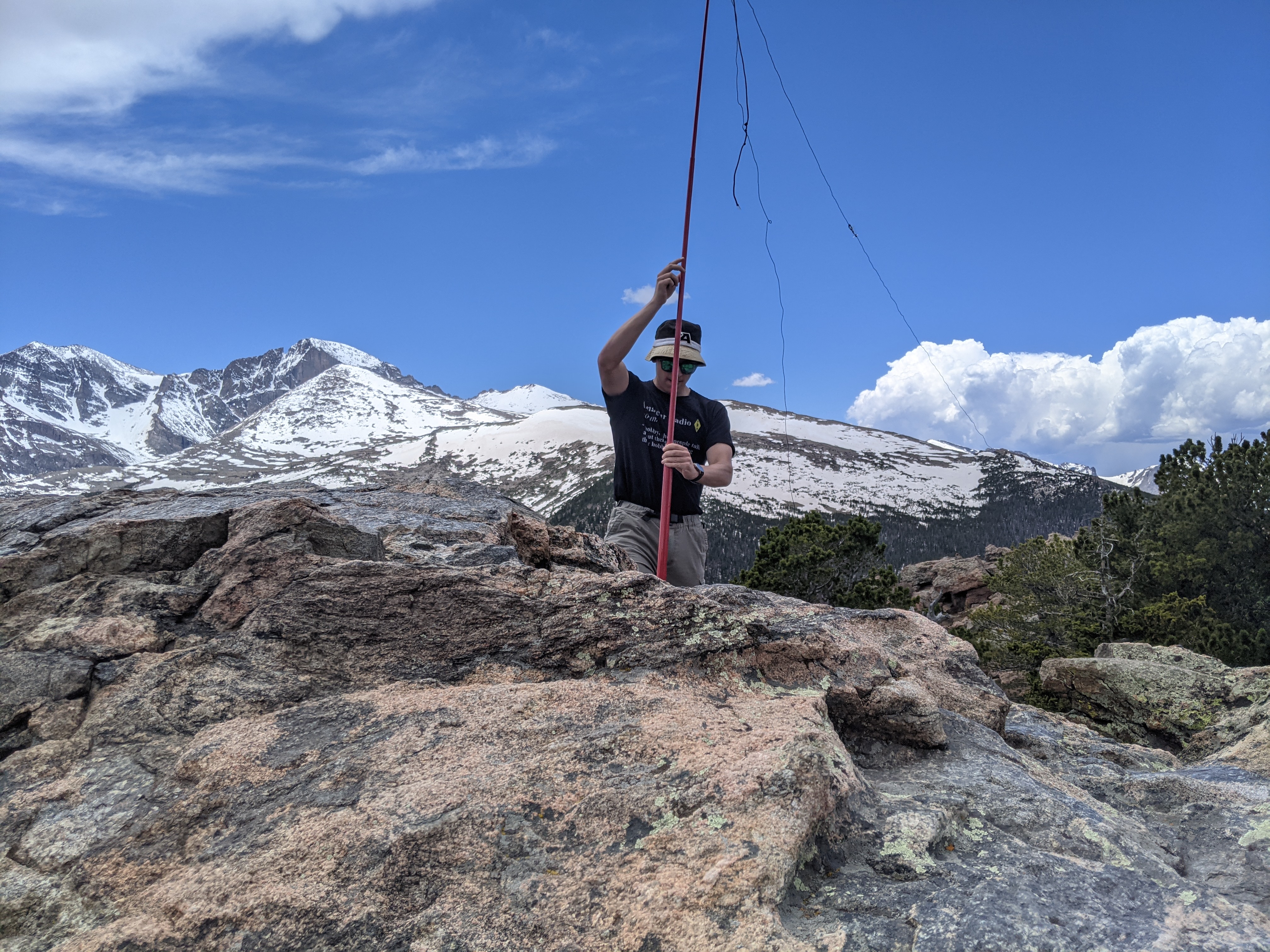
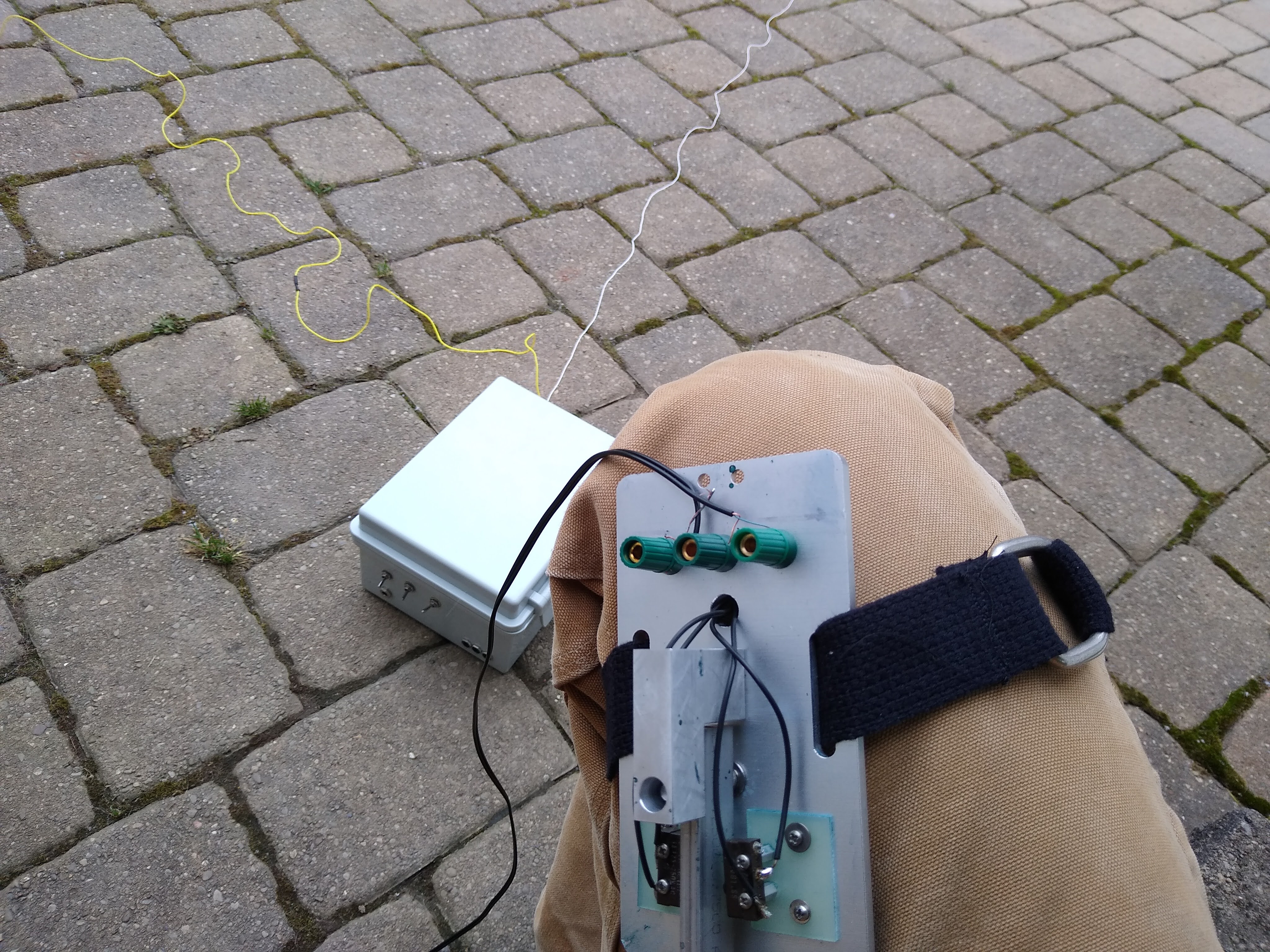
But it was way too heavy and bulky. I needed something that poked inches, not feet out of my pack. Enter KE6MT, who recommended Fishing poles on Ebay with just a little modification for antennas.
Field Test
I used kite string to epoxy some guy lines and heat shrink for friction against rough surfaces. I haven’t used the guy lines yet, as I’ve only ever tied it to fenceposts or jammed it in rock piles at the tops of summits.
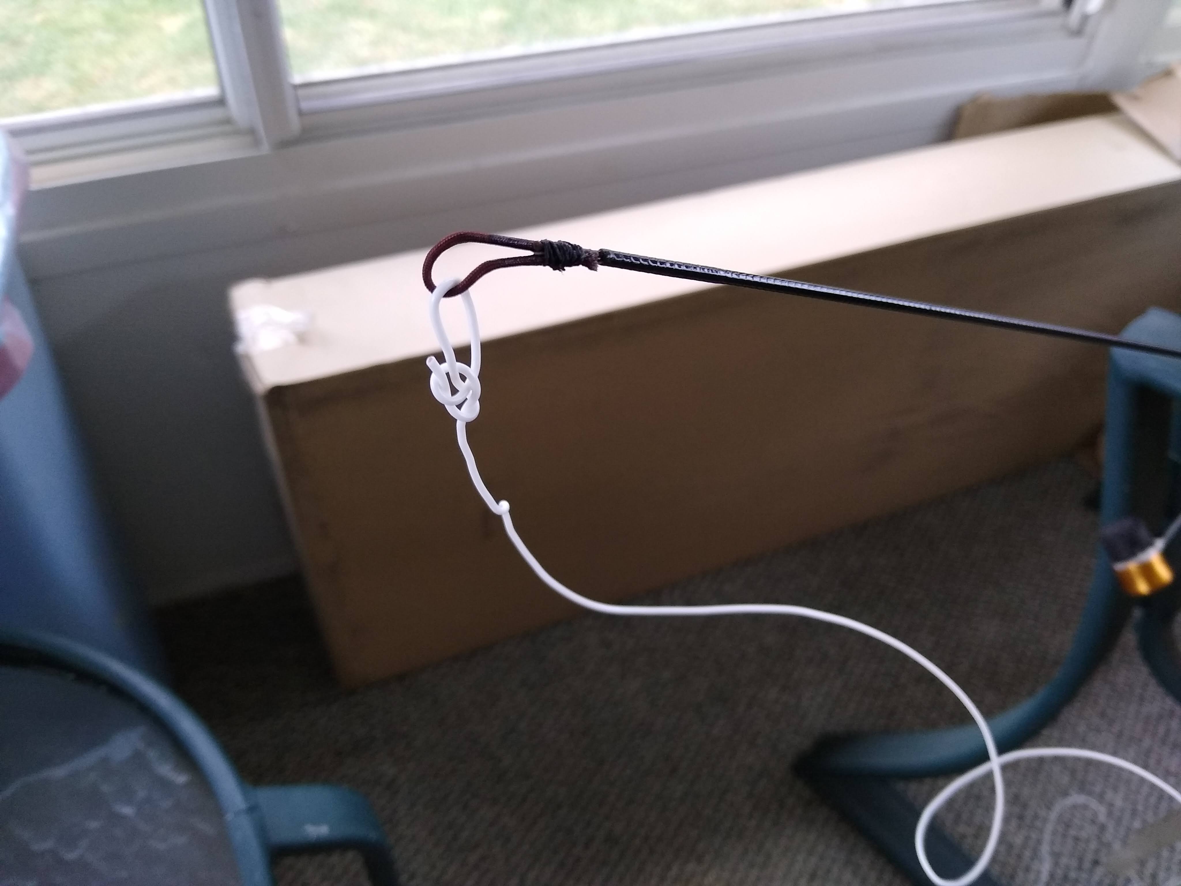
The chief problem here is that any weight will significantly affect the mast. My solution to this issues was to 1. superglue the first section inside the second section, and 2. fashion a loop out of the very top “fishing nylon” so I could secure my antenna.
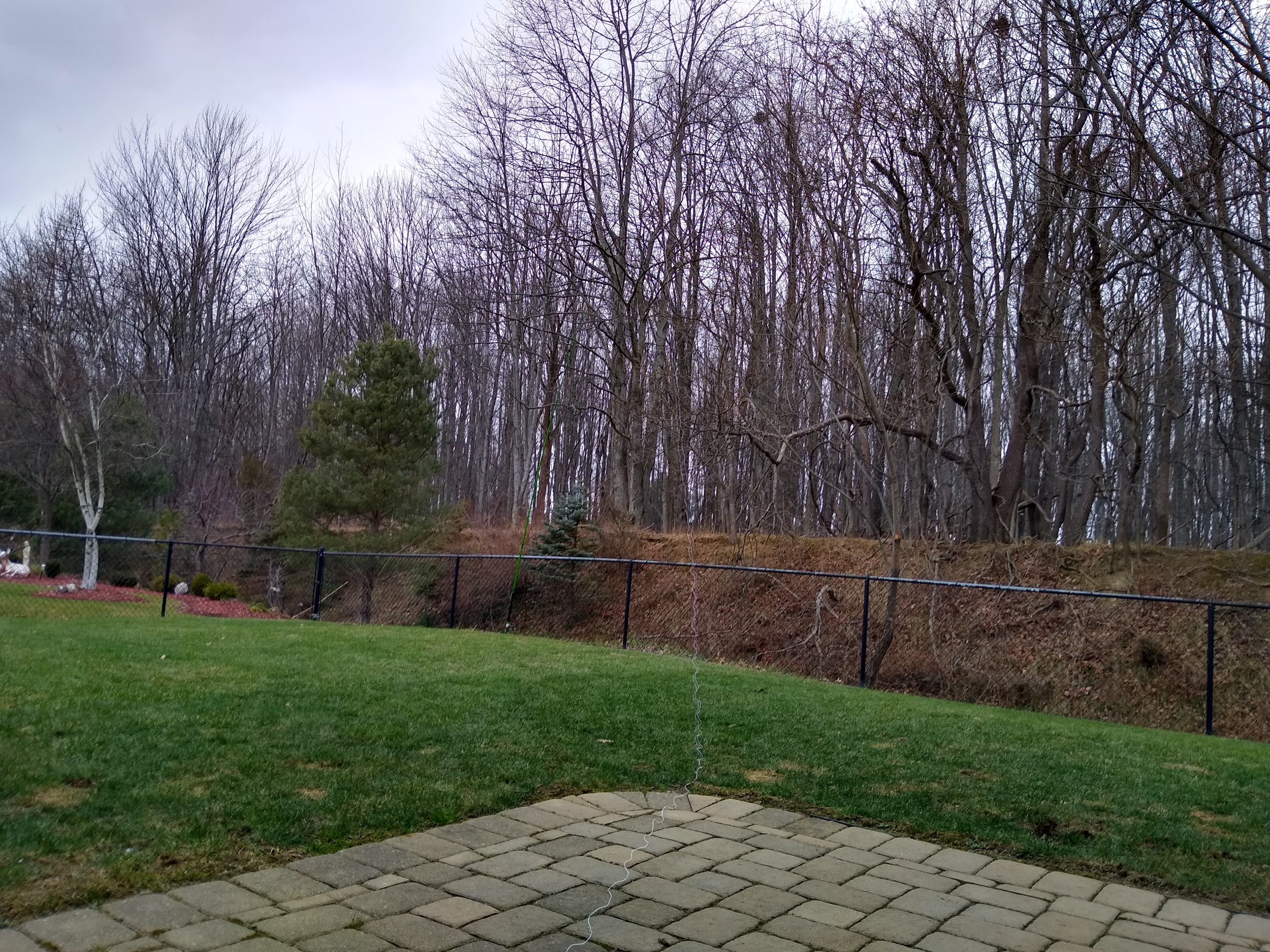
A field test in my backyard confirmed my success. I talked to Mike K1ETA in Rhode Island from my backyard in OH using 10W:
Overall the setup is light, quick to deploy, and minimizes strain on the mast. I haven’t had a failure with the 4 or so excursions I’ve been on, but I get a little queasy if I look too long at the tip bobbing in the wind.
Loose End 2: Homebrew Sideswiper CW Key
I’ve always found CW fascinating. You need just two signals to send messages across the world. These messages are generated by just three metal contacts - where you place these contacts is entirely up to you. I’ve seen some odd examples, and even made a capacitive touch circuit, but was getting many failures at the top due to stray capacitance. Many pros use some 3D printed lightweight design, but I figured I could homebrew a simple design.
I chose a sideswiper for ease-of-use, but also for precision. Some of the fastest CW coders use sideswipers instead of iambic paddles. I also figured I could ball my cold hands into a fist if I ever got cold and still be able to operate. More so, if I had one failure, I could turn the other half into a straight key ala HST (for 1/20th the cost).
Construction
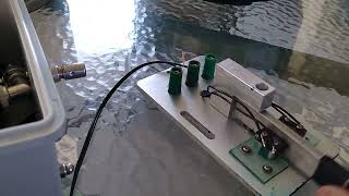
The key is made out of machined aluminum. The majority of the work was done by my friend Bob WB3EFT and features some milling for the center lever and aluminum stand.
The lever sits on a ball bearing core. Its keying is done by simple push switches with a reliable tolerance. The buttons are actually adjustable with some washers and screws on the base. Lastly, everything connects using a common stereo cable fed into three banana plugs.
The device mounts to my leg with a simple cloth belt. I find it stays in place while operating but slips around if I walk - I’ll probably need to add velco or some other method to keep it in place. The belt buckles are heavier than the rest of the unit!
Field Test
The field test worked well. I can easily send off 18 WPM (my cognitive limit) for picking up the key first time. A video of the key in action can be shown here.
Loose End 3: Trapped End-fed Halfwave Antenna
Lastly, I wrapped up the season by building an End-Fed Halfwave antenna. I hope to use it as my main driver out on the summits. Currently I use a 41/20ft random wire and have reached the world (France to NZ), I want to save a little more power.
Inspiration
Despite some criticisms, the EFHW is a popular choice among SOTA operators for long-range coverage. Numerous amateurs have taken their stab at the antenna, including WS0TA, and KT5X. Adam K6ARK has several videos on the EFHW, including a balun and trap build guide.
The EFHW itself is a balun matching a half-wavelength of wire at a resonant frequency. Ideally it requires no external tuner. Traps are filters that replace links; it allows for multi-band operation without lowering the antenna to change links.
The chief concern with these elements is the amount of testing. You have to be precise and tune every element; difficult and time-consuming if you are a novice.
Balun
Building
I followed KT5X’s guide for wrapping an FT-50-43 toroid with magnetic wire. I used a surface-mount capacitor rated for 1kV to reduce lead capacitance by axial leads. The semiconductor shortage might make these harder to buy - buy 2x what you need in case you want to build a spare. Also, pay attention to the profile of the SMD. You won’t be able to see anything below an 0603 profile. You can remove the magnetic casing by just flooding solder onto the wire; the flux helps remove the enamel. A lighter works fine too, but I’ve found the wire is more brittle if you use a lighter instead of removing the enamel and tinning simultaneously.
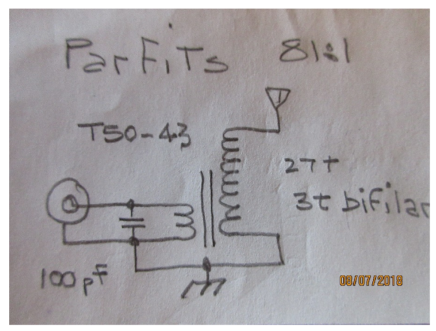
Schematic for EFHW. I wrapped 30 turns + 3 Bifilar turns
To wrap the wire, I took about 4 ft of magnetic wire and folded back the first 8 inches. I used a pencil to corkscrew-wrap this first 8 inches. This is my bifilar wire. I wrapped 3 bifilar first, then took my long end and wrapped the additional 30, ensuring adequate spacing throughout the toroid. I was more concerned with the endstate than the build process, but Adam has a great video if you want to learn how to wind.
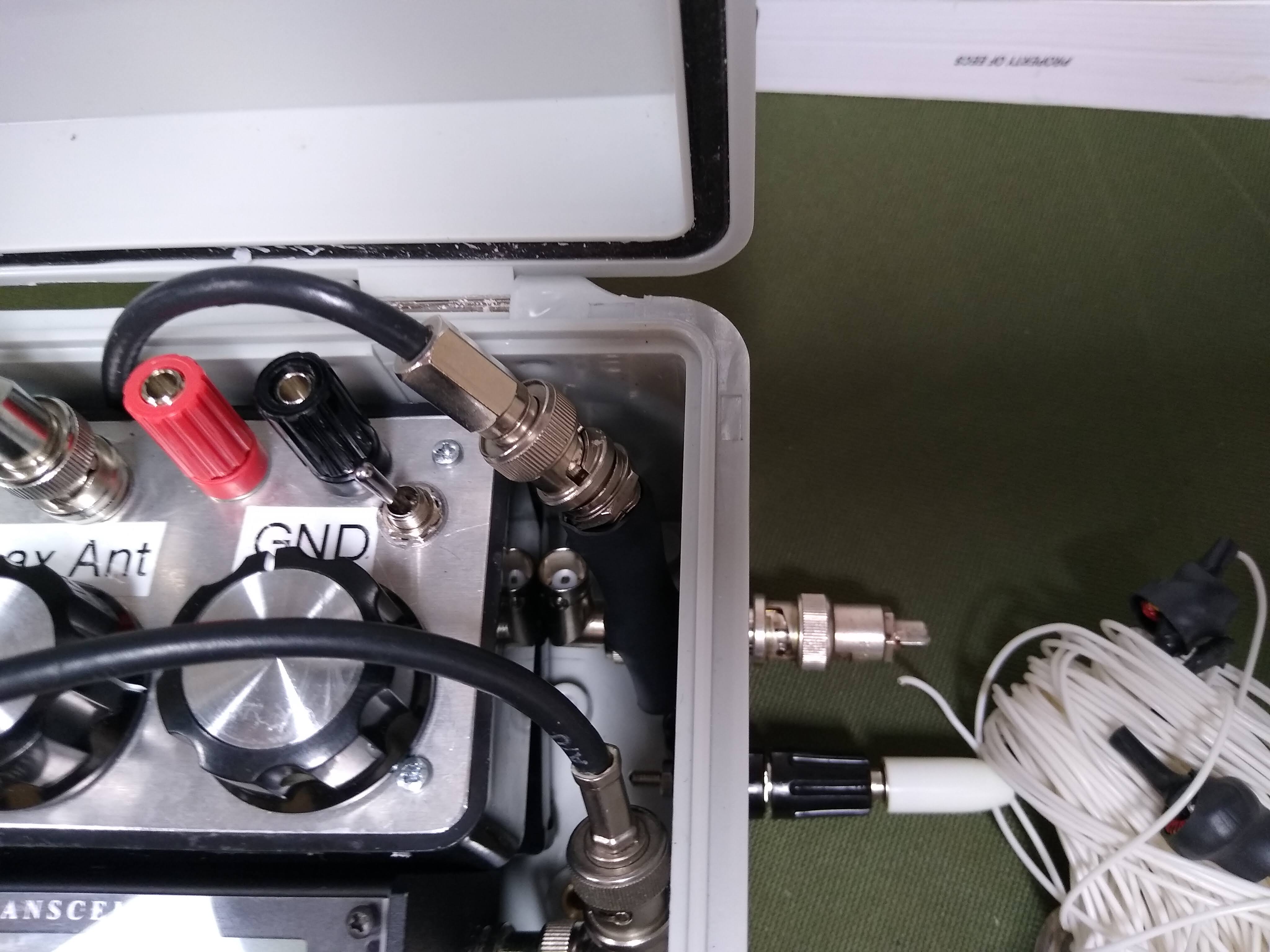
I soldered this onto a Female BNC connector, because I wanted to mount it inside my case. It connects with a short length of coax to the radio, which is much easier than the male “solder-window” types mentioned by Adam. However, I will probably be roasted on a pike for using a coax (re: counterpoise).
Tuning
The part many overlook is the tuning of the balun. Yes you will add and subtract wire lengths, but you need to add and subtract turns on the toroid. To do this, pick a frequency midrange of your ideal band. I designed for 10/20/40m (something I’ll regret later, but I was excited about the sunspot cycle), so I picked 20m - 14.100 MHz.
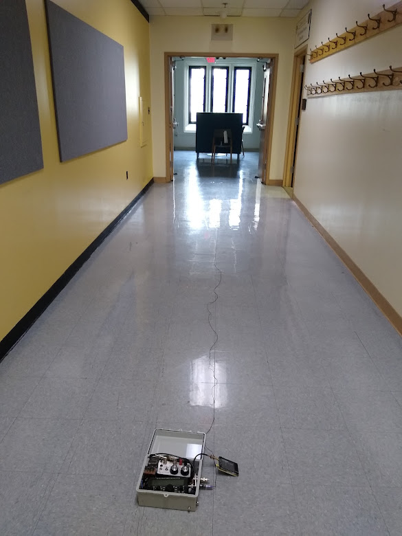
Get a spool of crap wire and connect it to the magnetic wire. My antenna mounts inside the wonderful Case-X2 so I soldered a banana plug on a spool of 22gauge. Secure your spool and connect your BNC connector to a VNA - I have the nanoVNA. A test setup looks like this:
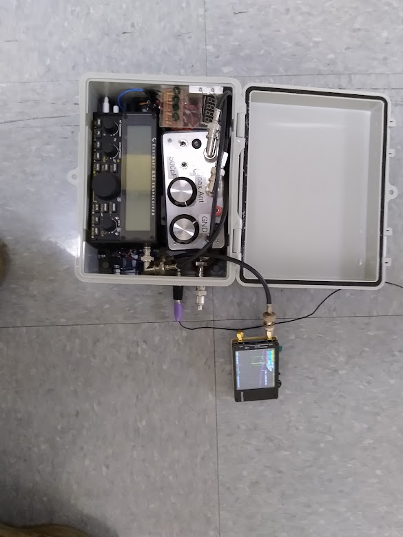
NanoVNA in the case
 The spool off in the distance. Get if off the ground!
Walk backwards with the vna until your SWR minimum is at your desired frequency. Here’s what mine looks like initially. Pay attention to the impedance given at the SWR point:
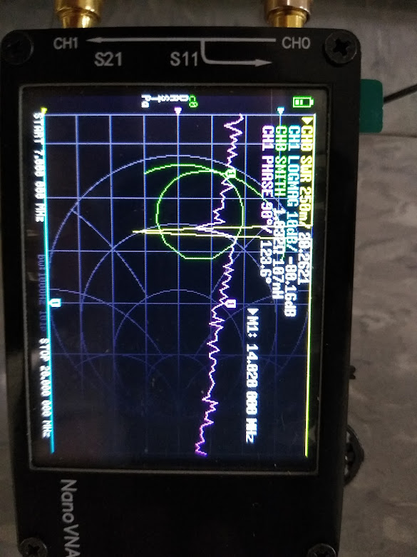 Not great initial results
Now, add or subtract wire turns to get you to 50 ohms. Remember the initial half-wave has an impedance reaching into 3,000 Ohms, so to get a higher impedance, take turns off. To subtract impedance, add turns. After some adjustment:
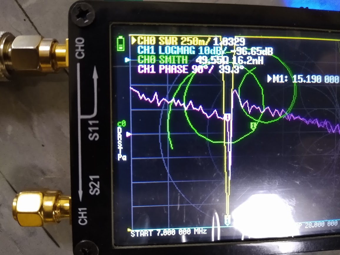 Back In Business
Now epoxy and wrap in shrink wrap, and you’re ready for the next step (the traps!)
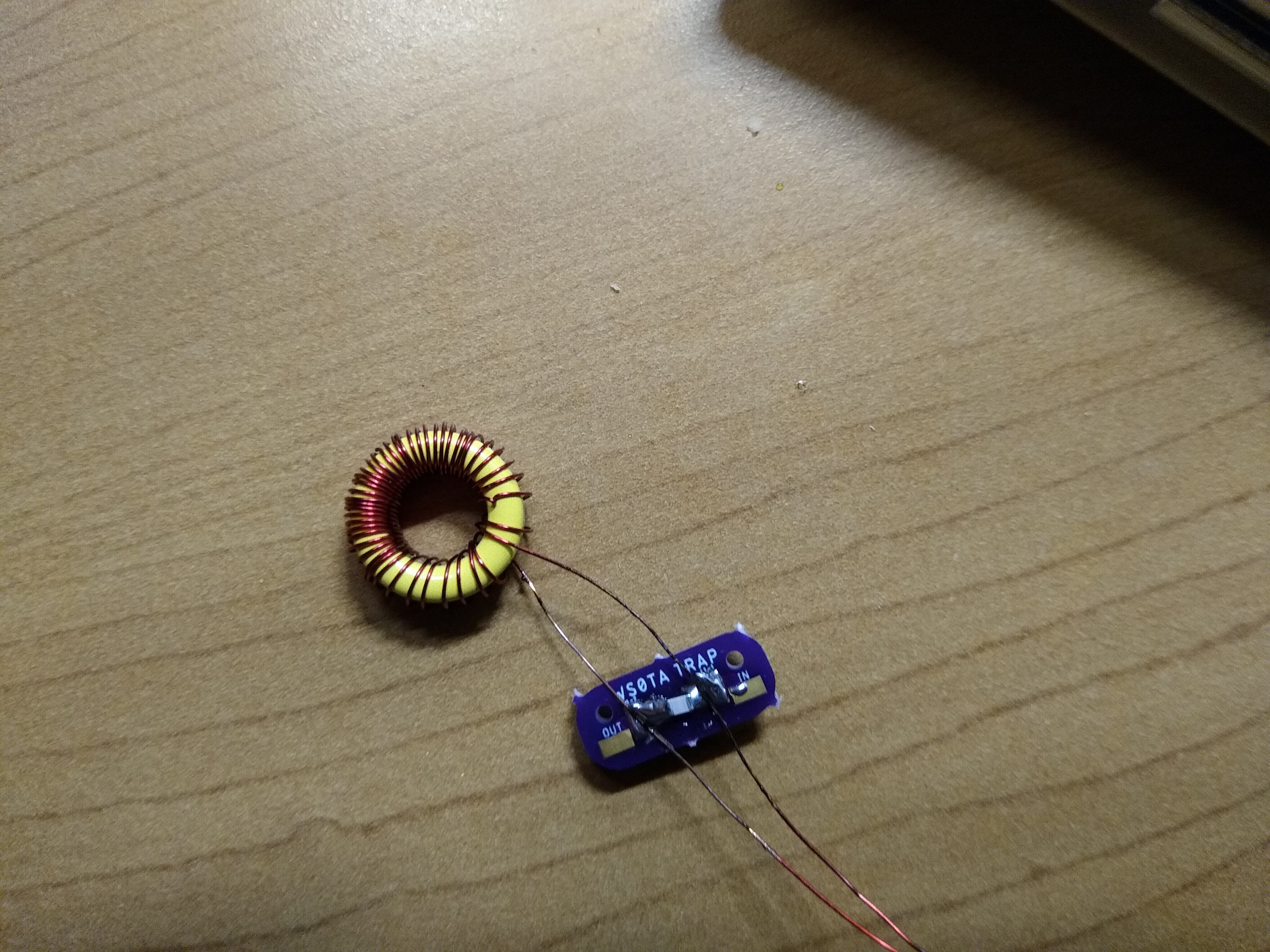
Traps
Working with surface mount components, threading needles with magnet gauge, and tuning an incredibly small bandwidth? Some might say…

They also might say it’s a trap. With patience and foresight you may enjoy making these.
Construction
You will need:
- Magnetic Wire
- FT-50-6 Toroids
- SMD capacitors rated for >25V
- Spare protoboard or WS0TA’s Design
Use this online calculator to guess the amount of turns and capacitance needed for the filter. Get to an inductance with 30 or so turns - that’s the max you can fix. Wind away, and keep plenty of extra lead length just in case.
Plug that inductance value onto this other calculator to find a resonant frequency near your desired band frequency. Now, much discussion has been said on whether the reasonant frequency is above or below the frequency of interest. Logic to me says you want it slightly below the frequency of interest, but guides say it needs to be incredibly close (still below) the lowest frequency.
After you find that capacitance value, select the capacitor needed. I used about 14-16pf for 40m, and 8-9pf for 10M if I recall correctly.
Tuning
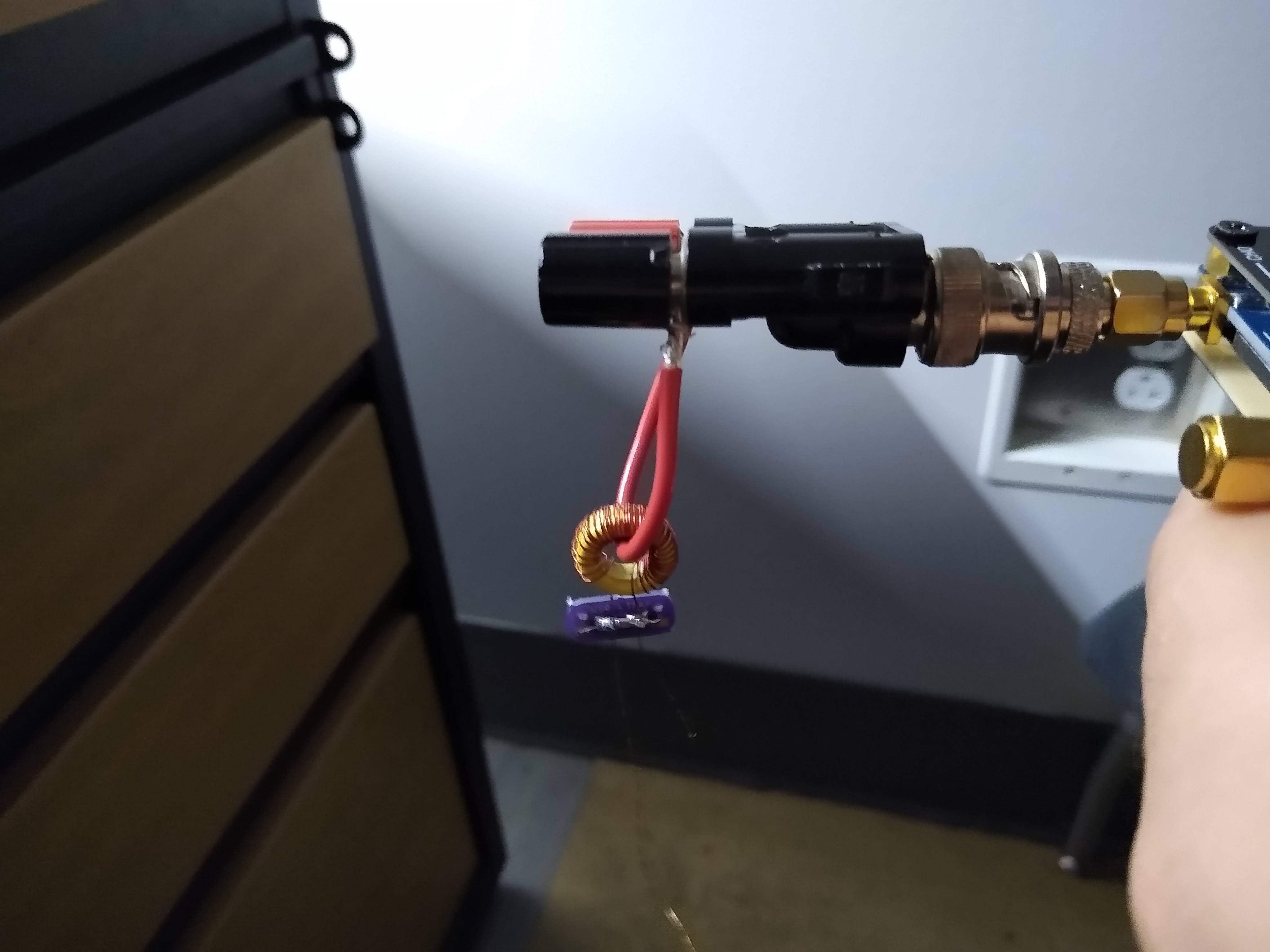
This is where the fun begins. Use a common banana jack/BNC connector and thread the completed trap through it:
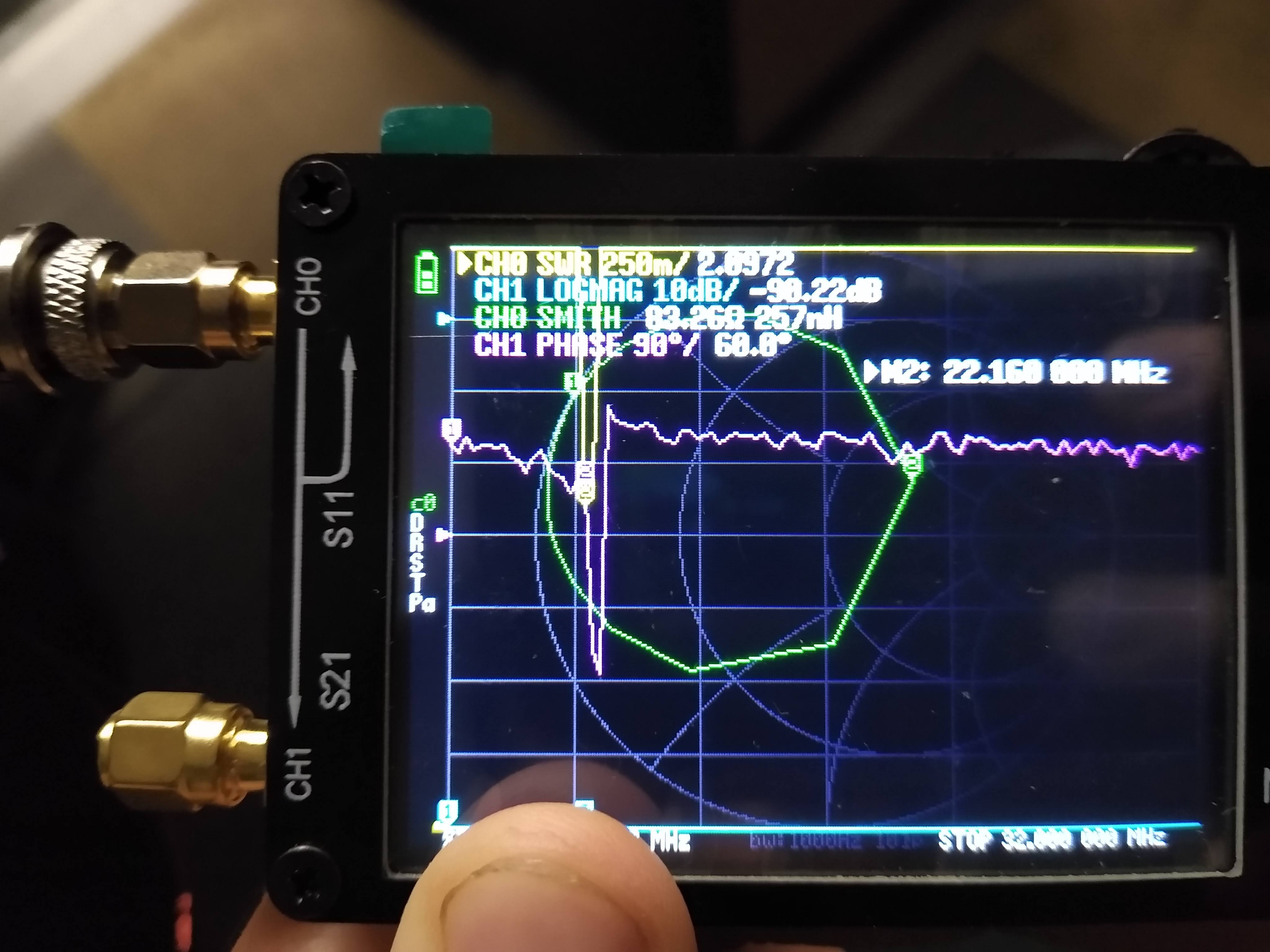
You’ll then measure SWR and get a close resonant frequency. Here I am initially on 10M:
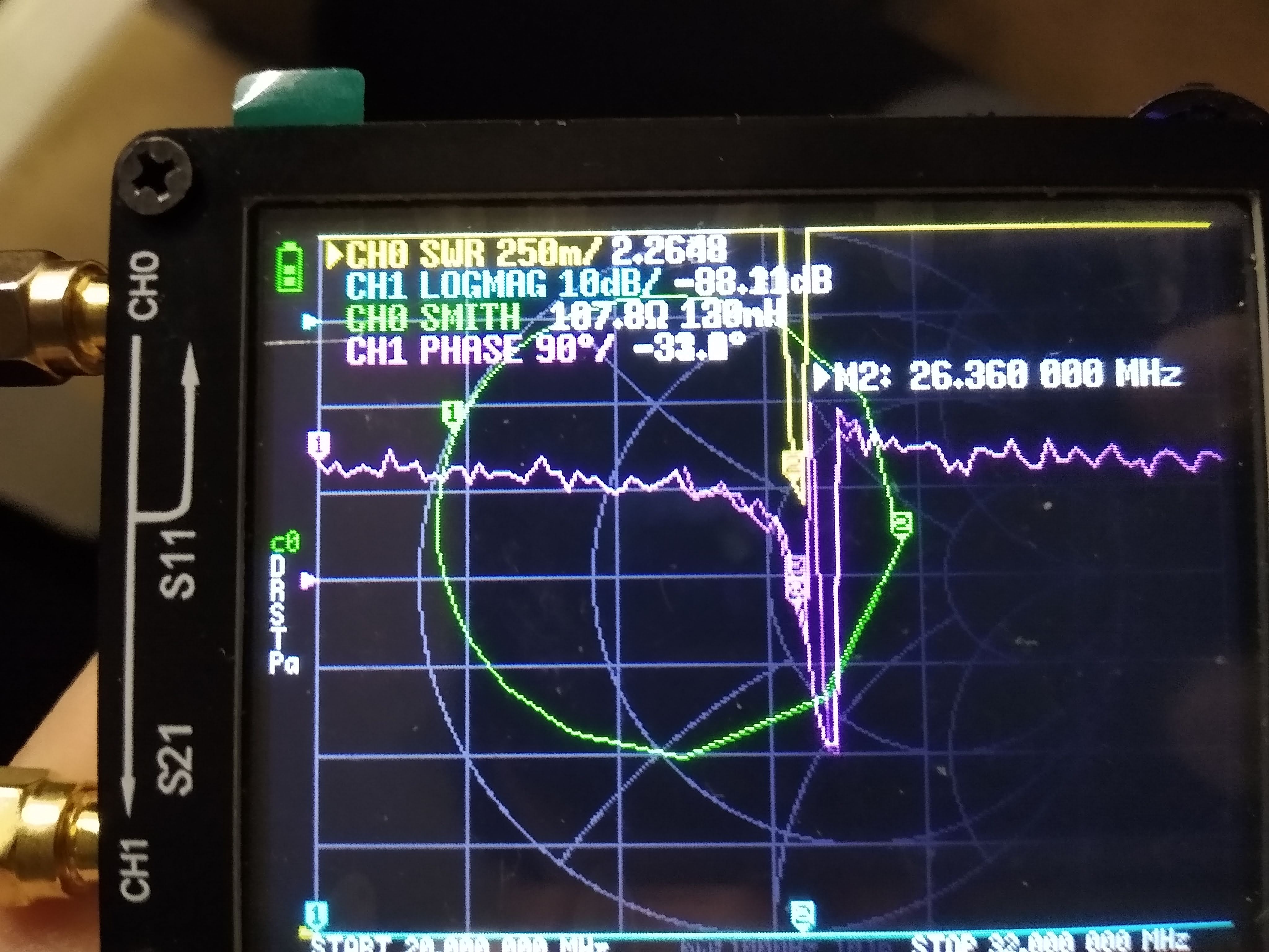
Subtract turns to raise frequency. Here it is adjusted a little bit:
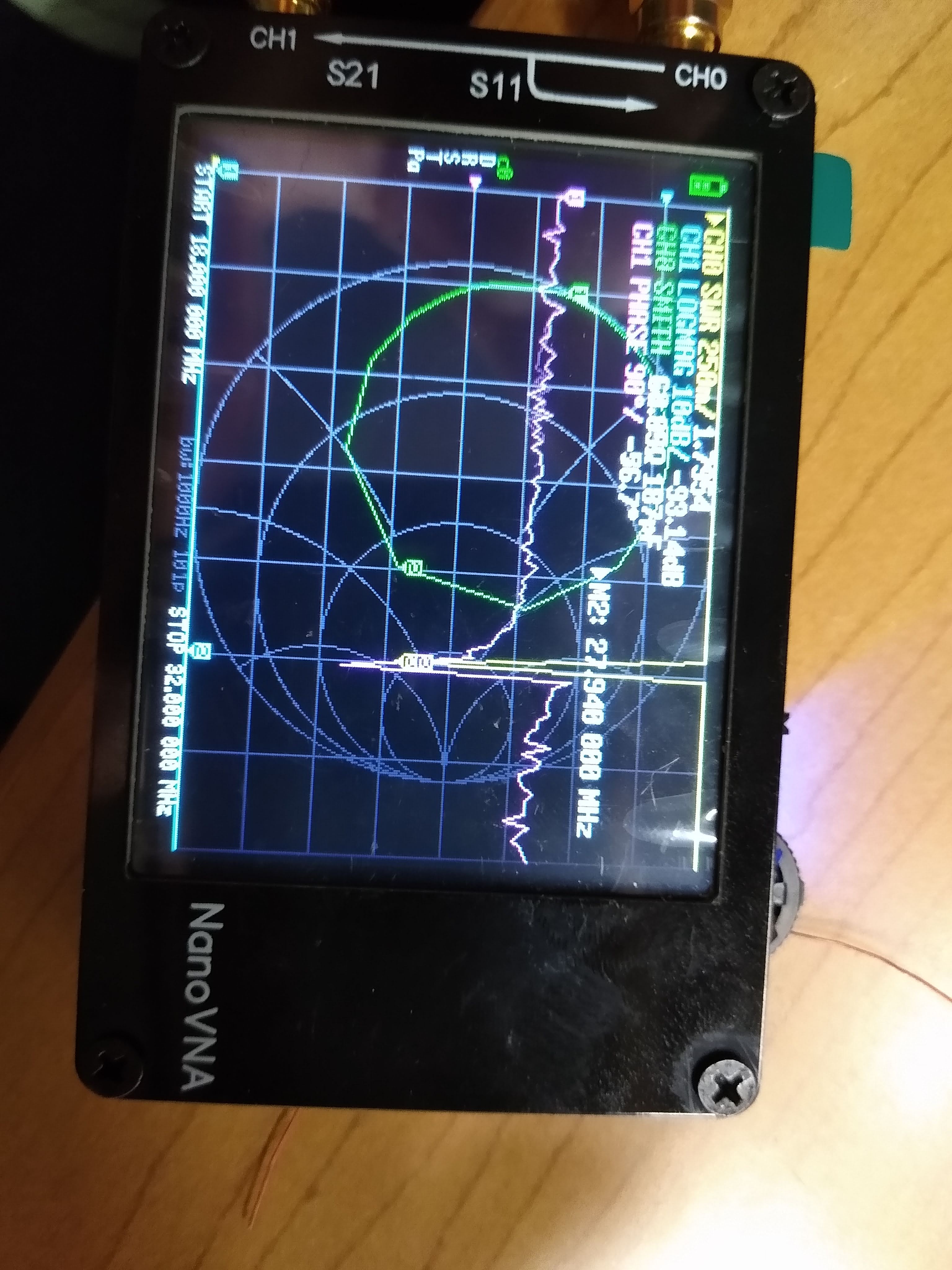
Final adjusting:
Do this again at your middle resonant frequency (so 10M and 20M) then shrink wrap for great results.
Wire Lengths
Like I said previously, the best SWR for the balun is determined at a resonant frequency. First, I get a spool of similar “crap” wire, then affix the spool to a solid point while stil letting it unravel. Walk back a half-wave distance and view the EFHW SWR. When the SWR is lowest at your desired operating frequency, mark this distance in the crap wire.
With this length in mind, cut a same length of high-quality wire (I use stuff I bought local, but some recommend wireman). Solder the first trap to the end of this.
Continue with the second wavelength still using the crap wire. Subtract this length from your first length, and you have your second length. Solder the trap again (with heat shrink), and you’ll repeat the same steps for the third wire. No trap on the end of this one.
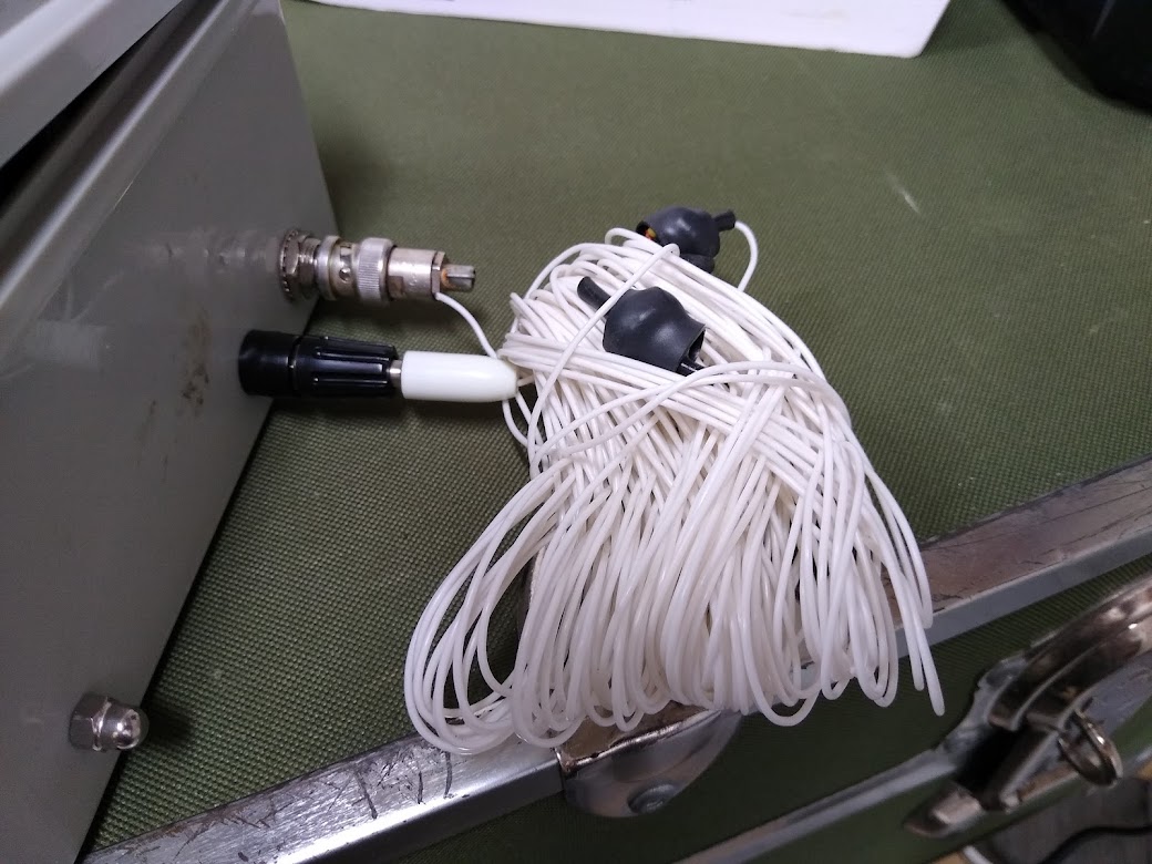
The end result is an effectively tuned EFHW! Here are some more pictures of the device in my case:
Conclusion
Ham radio is a technical hobby. As a ham, you’re able to build tools to suit your use case; summits-on-the-air is one of the most constrained experimental setups available. A little RF knowledge with a lot of dedication and testing (and magnet wire) makes for a successful daily driver.
-N2WU