A new, self-built diy case for the Elecraft KX2 and tuner useful for SOTA and expedient HF operating.
Introduction
If you’ve seen my 10 or so SOTA posts so far, you know I stand by my custom setup of a tuner, radio, and LiPO Battery. However, after several excursions I realize I have the same reoccurring problems. I have to connect my daisy chain of devices together out exposed to the elements at the top of the summit. I wanted an enclosure that would accomplish the following:
- Fully enclosed - no daisy chain or wires that could get snagged (save the antenna)
- Fit all of my components inside (elecraft, tuner, and battery at a minimum)
- Weatherproof for snow / mist / various conditions I’ve experienced at the top of mountains
- Allows me to plug in external devices (headphones, microphone, CW Key) easily
- Can fully operate with the lid closed
- Can fit in my 40L backpack with the rest of my hiking gear
- Doesn’t significantly change the weight of my hiking kit
- Durable requiring little repairs. Uses little glue if possible which may fail at low temperatures
- Has some quality-of-life additions, like a battery charge indicator, a real-time clock, and an internal key
- Can turn on/off additions for barebones QRO (albeit 10W) and long-duration operating
- Looks professional (at least in some aspects)
- Inexpensive (<$40) and buildable with junk-box electronics components
It’s quite a demanding customer request, but results in a high-quality, long lasting SOTA solution. This Thanksgiving I got quite busy with the build and was able to accomplish my design parameters into a significant upgrade. Continue reading for the DIY breakdown and full-featured list. I based my design off of K2GOG’s and Radio-Set GO.
Components
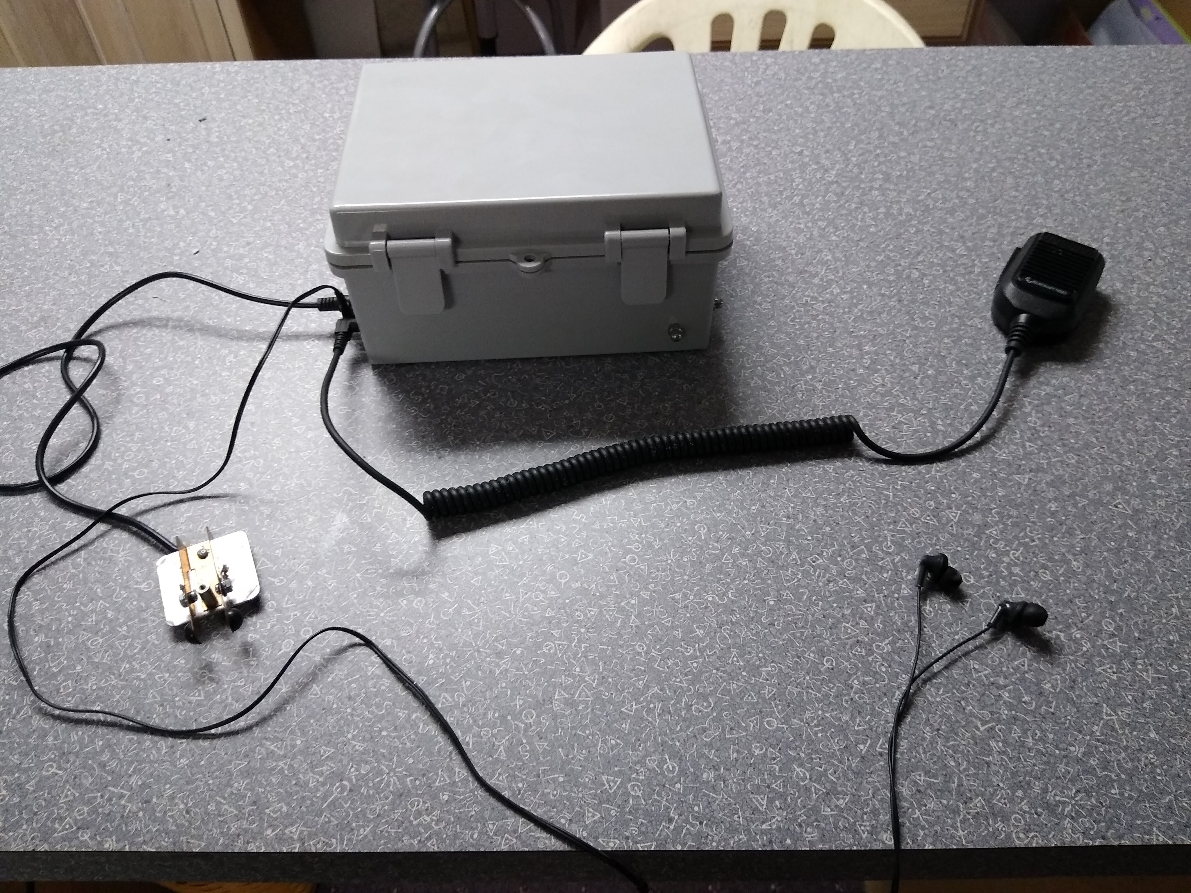
Here it is, in all its glory:
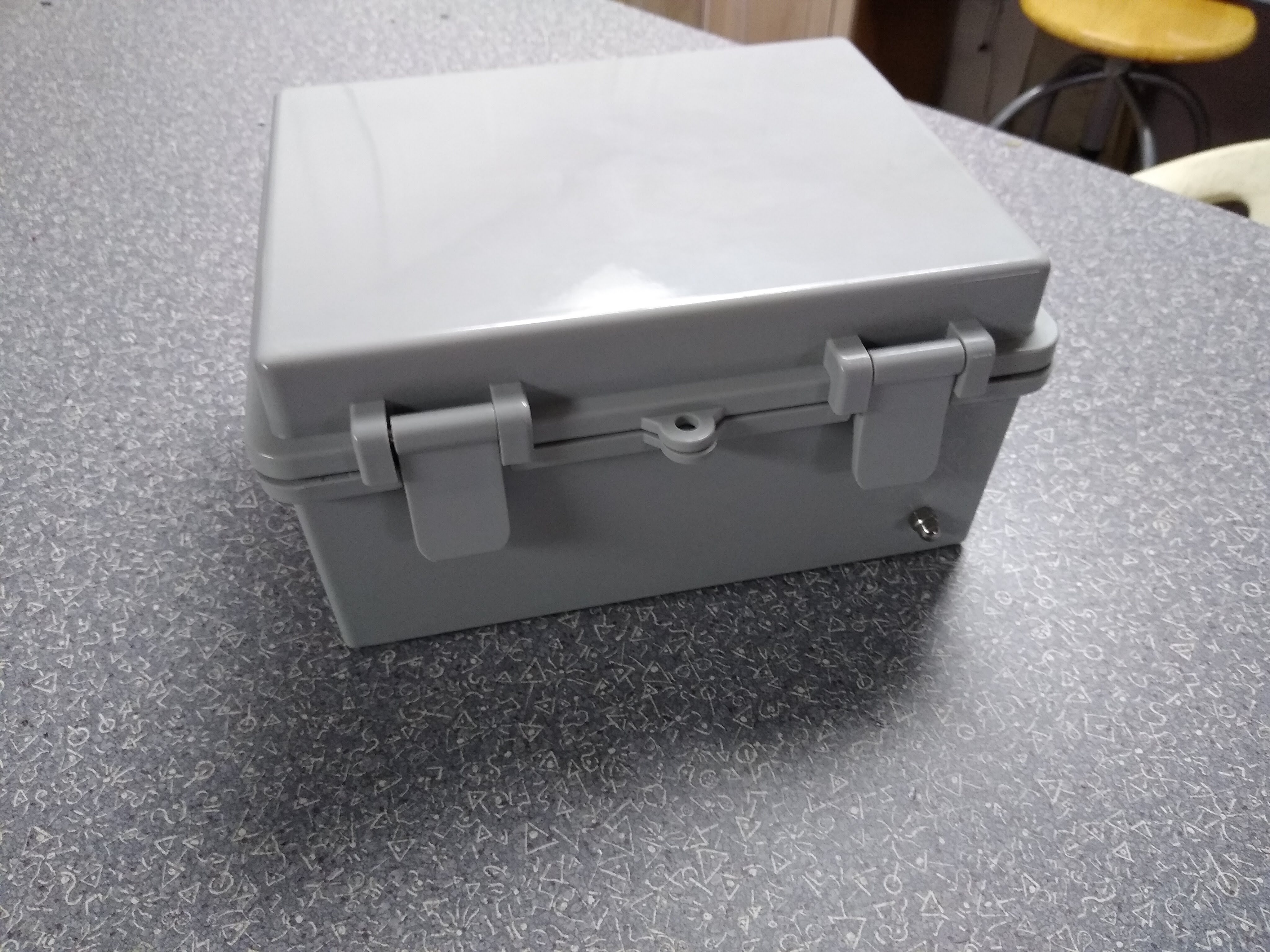 The Box
Of course it’s bigger on the inside

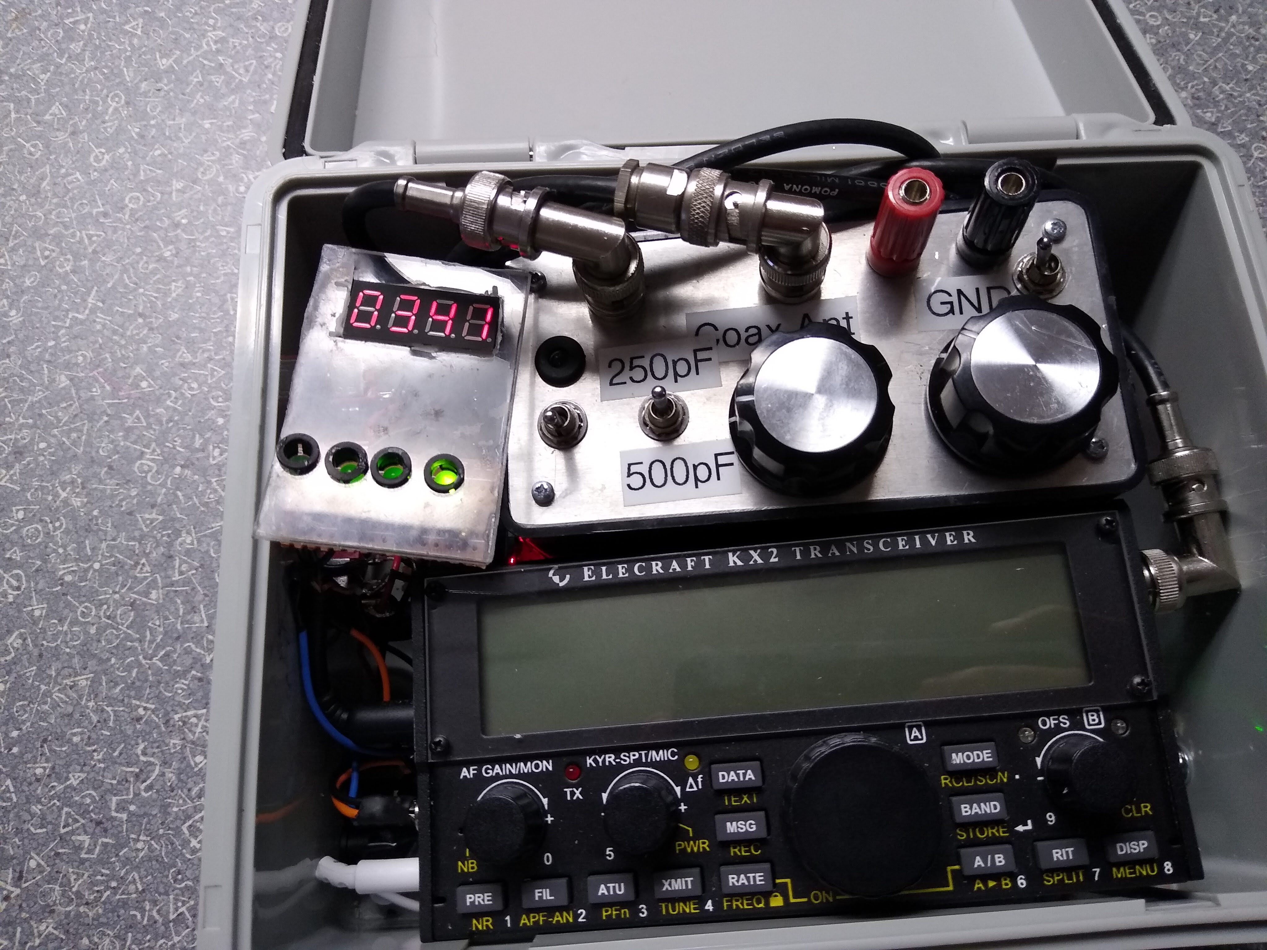
And here’s a full numbered breakdown of what’s inside:
- Battery Charge Circuit
- Battery Charge Indicator
- Real-time Zulu Clock
- Charge - Operate switch
- Aux power on/off switch
- Internal / External Key switch
- ZM-2 Tuner
- Elecraft KX-2
- BNC Antenna out
- Capacitive CW Iambic Key
And more views of the case:
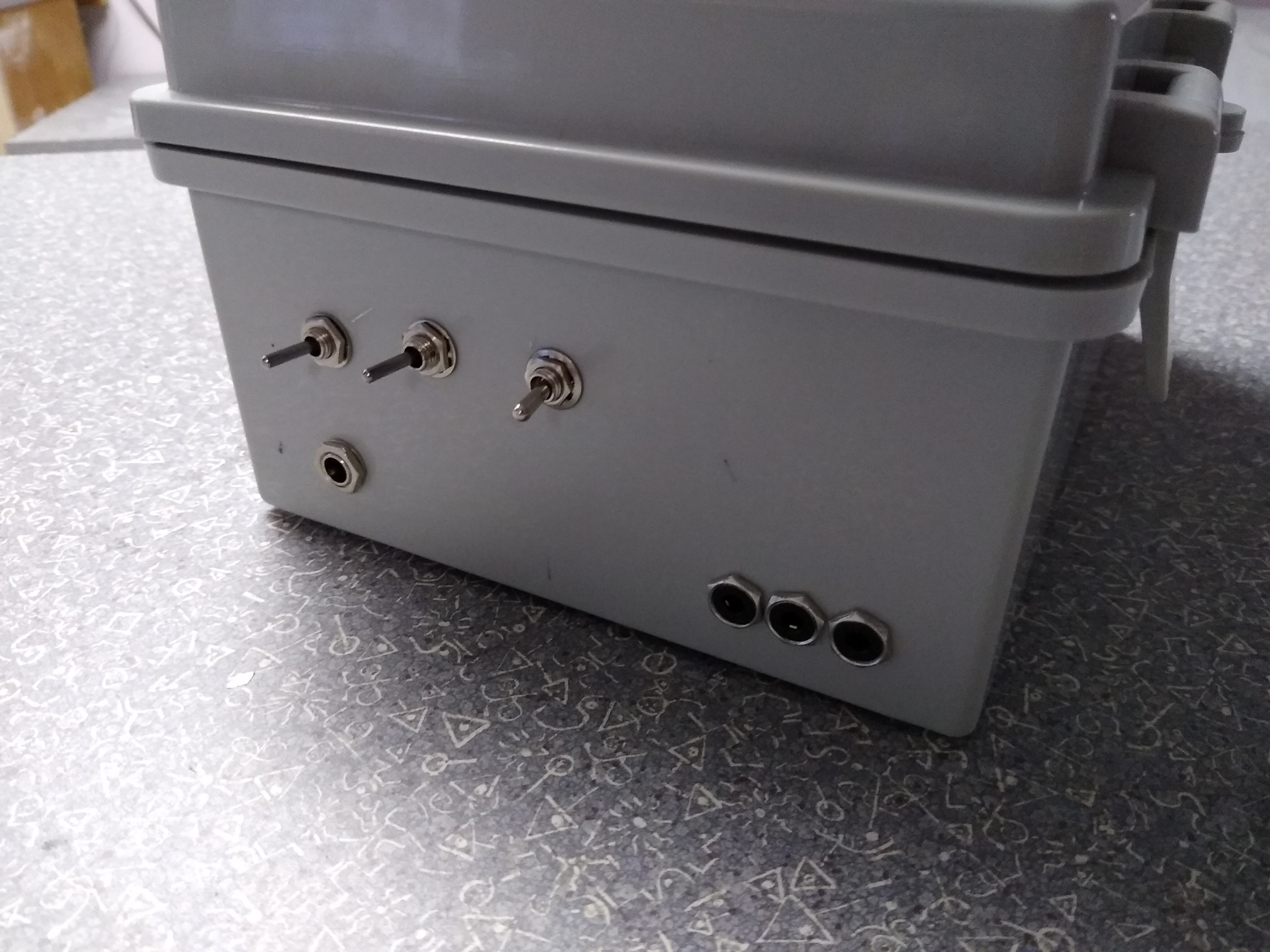 Switches, barrel jack input, 3 mic input
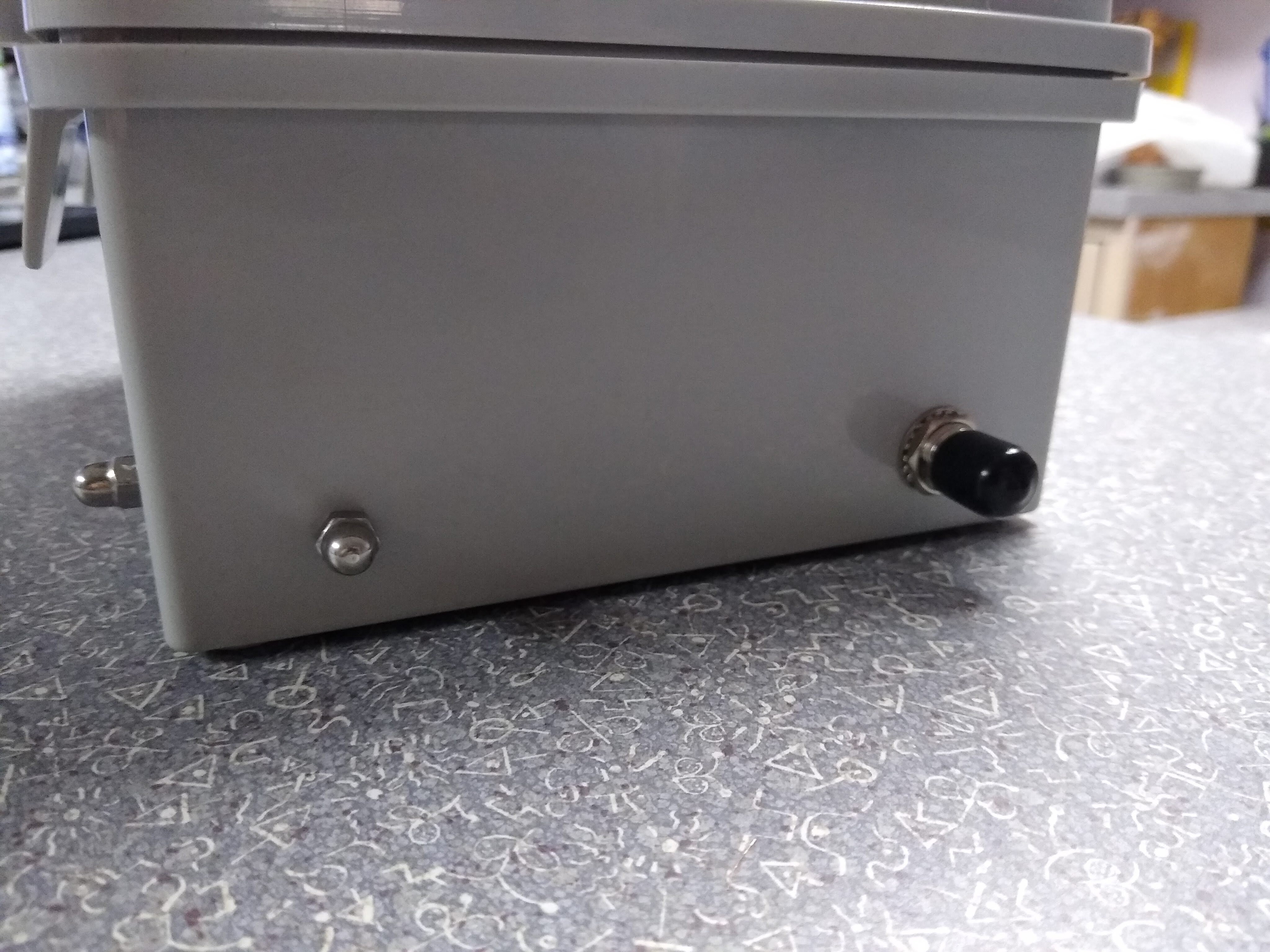 Other Side of the Case: capacitive touch key and Coax out
Overall, it took a lot of product design and prototyping before I settled on something with a good form factor and usable design.
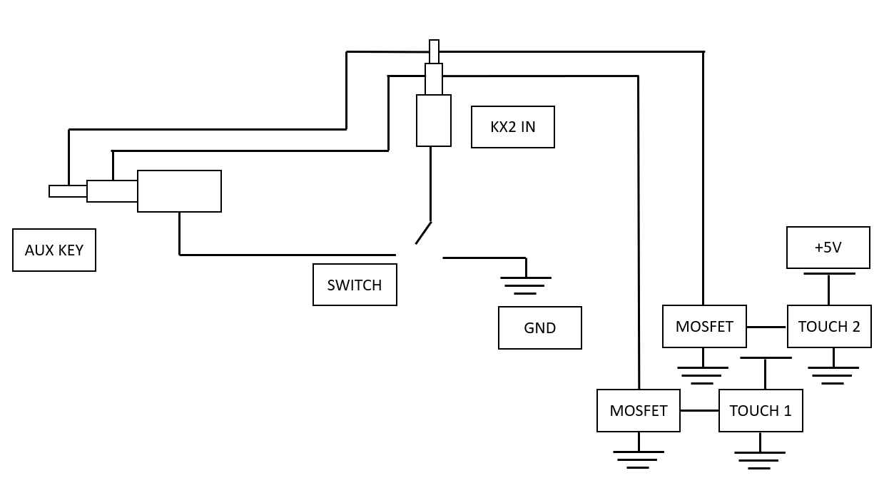
System Inputs / Hardware Connectors
The box has several layers and overlaps of components. Below is a block diagram for the system:
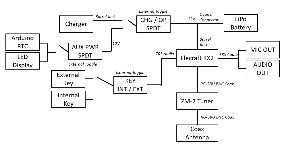
Note the inputs are either physically plugged in (antennas, aux cables) or user-selected (position of the switches)
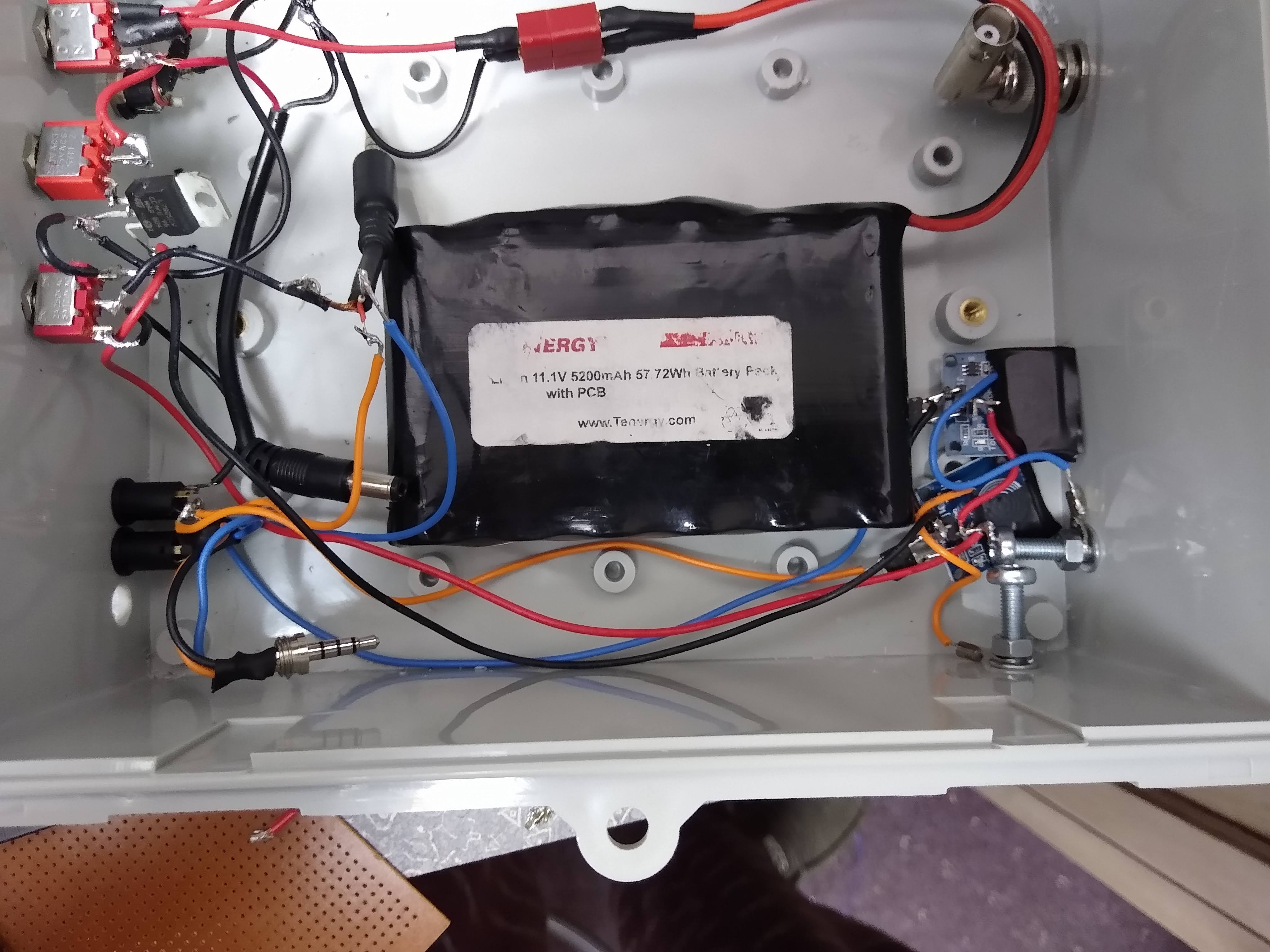
The box is a simple ABS case that would fit my elecraft (6” x 3” x 3” long) and my tuner (5” x 3” x 3”) inside with a little room. It was the most expensive component of the built, at $21.99. It has a relatively cheap construction but makes me feel not as bad when I drill, mark, score, and paint it. It has an O-ring seal and latches that will make it weatherproof for my uses.
For the switches, I used the universal SPDT toggle MTS-102 for 3 settings on the case.
Switch 1: Charge / Operate
The center pin in this switch is connected to the LiPo battery V+ that sits on the bottom of the box. One side is connected to a Barrel Jack Mount right below it, and the other to a barrel jack cable (for the KX2) and a wire leading to auxiliary power.
A simple schematic is shown below for the switches:
I recommend using a multimeter with the “connection” feature here to certify what connections are where. The DC port had different-than-assumed leads.
So, if I plug in my LiPo safe-charging wall mount into the box and flip the switch to “CHG”, then I can charge my LiPo safely within the box. if I switch to “Operate”, then I am plugged into the KX2 and have the option of auxiliary power.
I also have to point out that my LiPo is still isolated from the rest of the circuit. I attached a Dean’s Connector to it that gives me a degree of emergency separation or removal from the system if needed.
 Dean’s Connector, incredibly cheap and used widely in LiPo battery applications. Solder the female end to the battery for safety.
Switch 2: Auxiliary Power On / Off
As shown in the above schematic, I wanted the option to power on/off my external devices for longer duration operation. I rigged the same SPDT into an SPST so it simply powers on and off. This provides power in series to my Real-time Clock and charge display indicator.
I also connected all of my power grounds together. While this doesn’t provide as much isolation, it is a necessary compromise to avoid expensive and bulky DPDT switches.
Switch 3: Internal / External Key
The last switch uses the same SPDT to toggle external or internal (box) key. I connected the rings and tips together - a DPDT would probably be more beneficial here since I am only isolating the sleeve. However, it gives a degree of selectivity to the circuit.
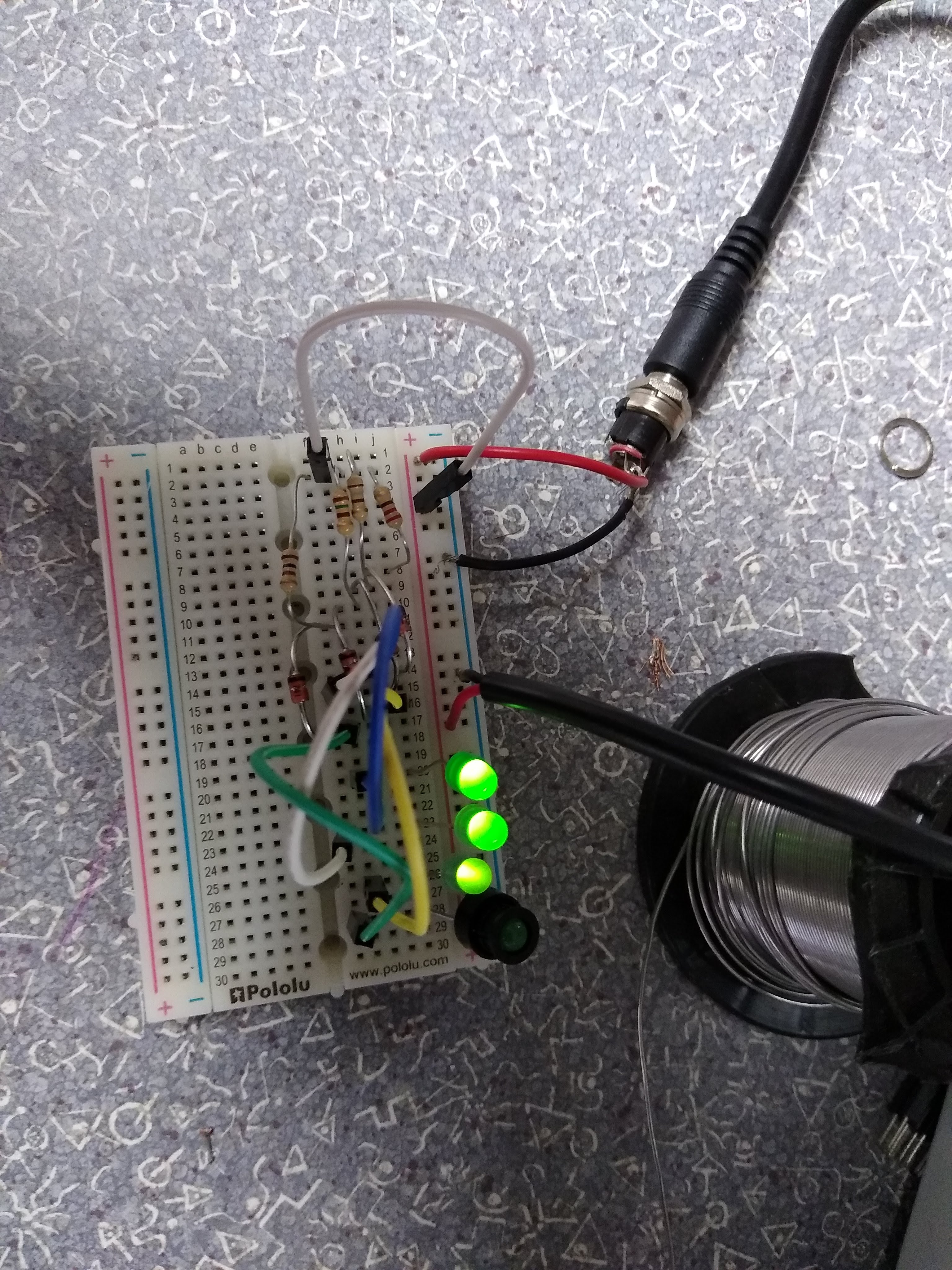
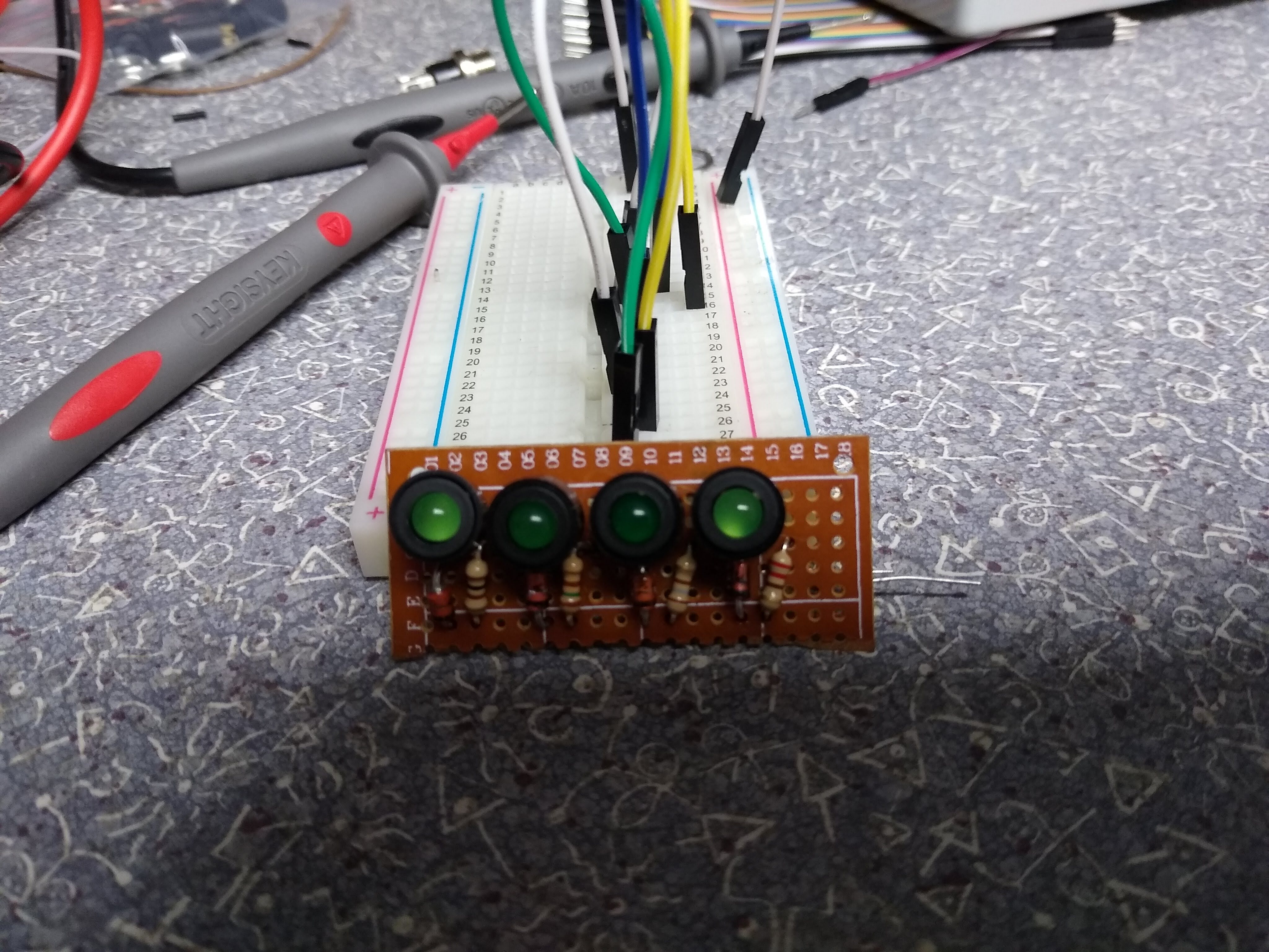
Battery Charge Indicator
For the first internal portion of the circuit, I used this guide for a 12V battery charge indicator. My battery is 11.1V, but is close enough to 12. It takes simple, low current-draw components and was easy to breadboard.
Here’s the schematic: Schematic
Here’s the circuit on a breadboard:
Transferred to cheap perfboard:
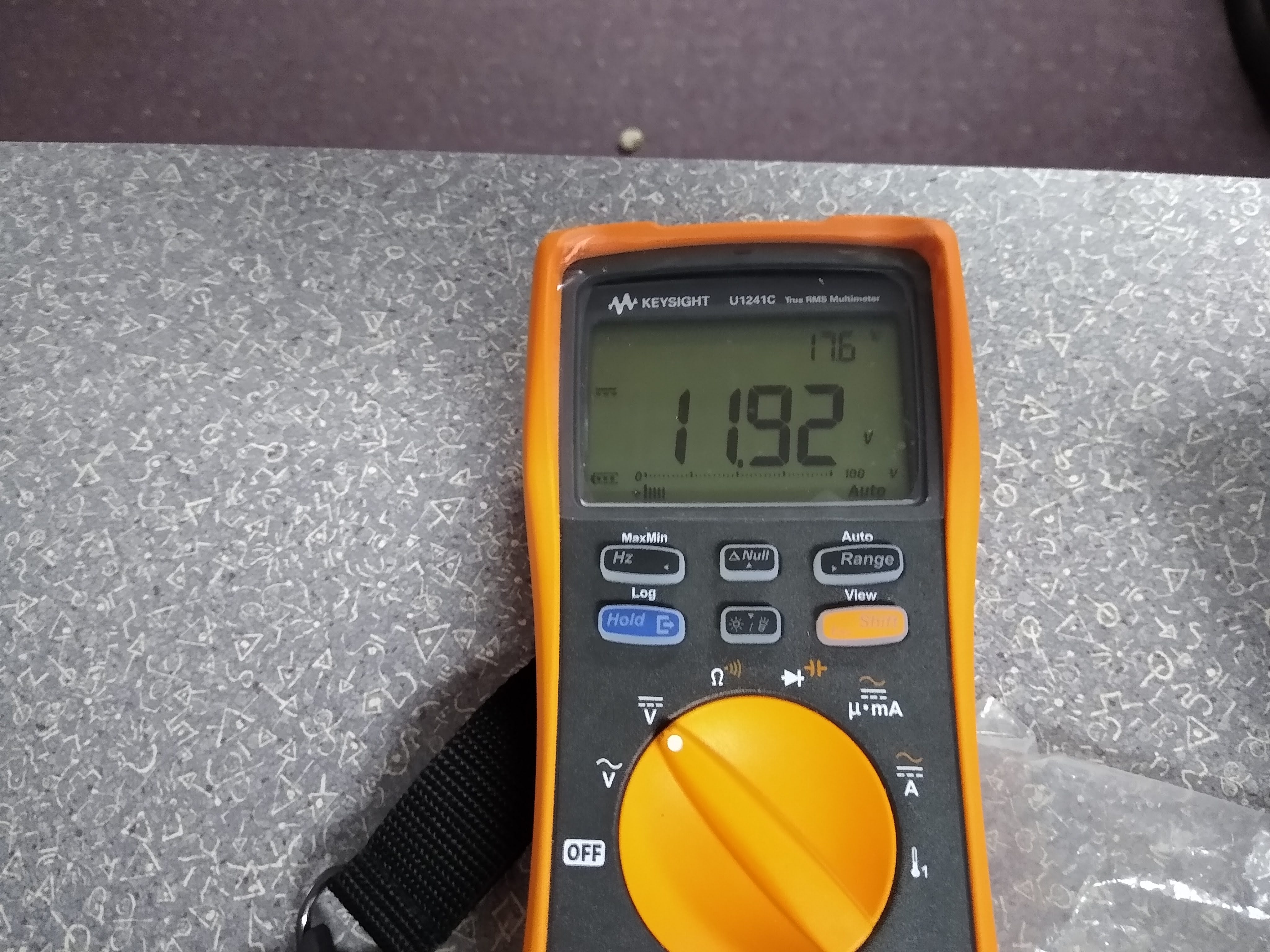
The voltage while connected to the circuit. I was concerned with current draw and possible voltage drop from the LEDs and Schottky diodes:
Charging Circuit
The other difficult part was figuring how to charge my battery without removing it from my case. Using the above schematic for the case, voltage would flow in or out depending on the switch configuration. The isolation ensures I won’t supply voltage to the wrong places. A schottky diode would allow me to protect from reverse voltages, but I did not want a voltage drop against my already low voltage.
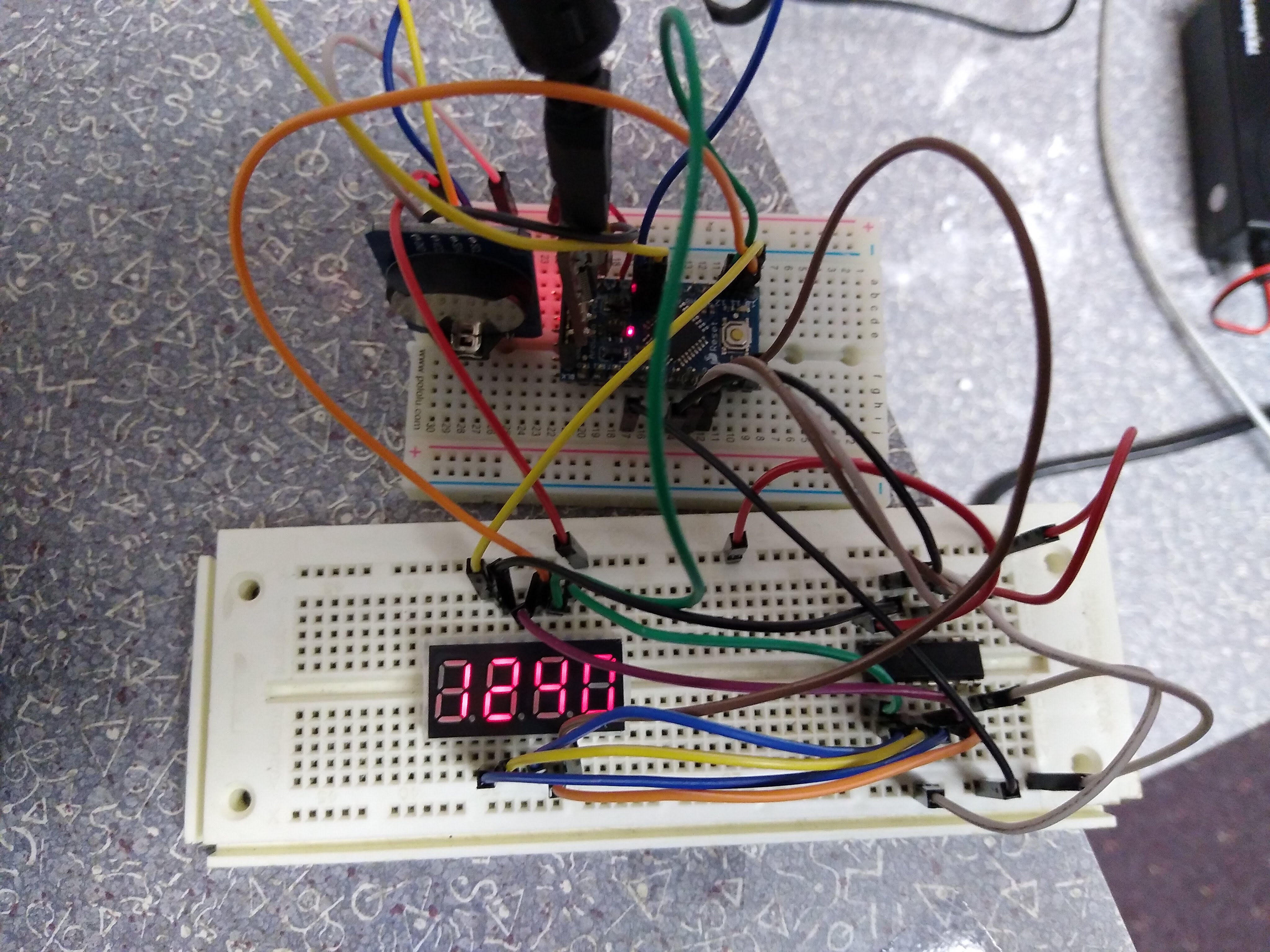
Real-time Clock with 7-segment Display
The other problem I always have on the summits is recording what time I make contacts. I used this guide to multiplex a 7-segment with an arduino pro mini. The components are listed below:
- A 4-digit, 7-segment display
- An Arduino Pro Mini
- A real-time clock
- A 74HC595 multiplexer
- A 7805 Voltage Regulator
Here’s the breadboarded circuit:
Here’s both auxiliary elements mounted in the case. I cut a rough piece of polycarbonate to fit the 7-segment display and the charging LEDs. For now it sits inside, but eventually it will screw into the side.
My code for this device is available here. I used software commands to actually set the zulu time, then recompiled it removing the startup command.
Your first compiling should look like this in the setup if it’s 0135z:
RTC.setHour(01); RTC.setMinute(35); RTC.setSecond(00);
Then remove the RTC.set() commands and re-compile as long as you have a coin cell battery in your RTC.
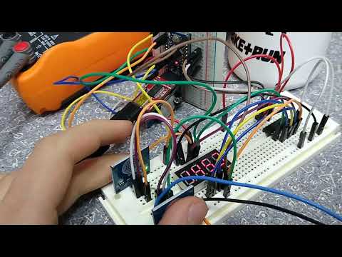
Capacitive Internal Morse Key
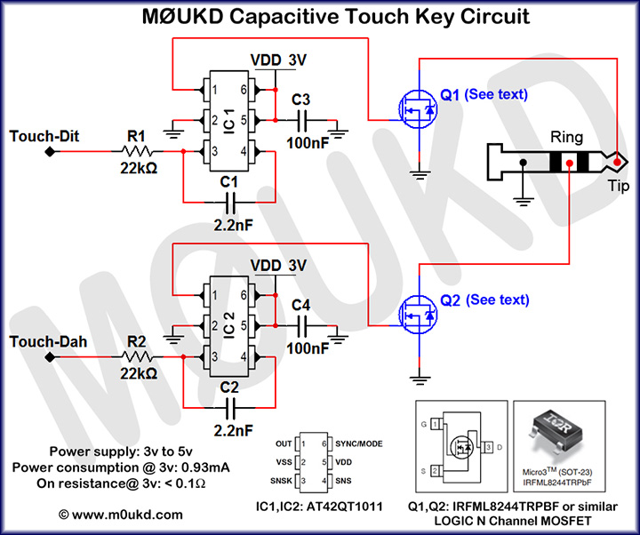
I also used the opportunity of an enclosed case to add a capacitive CW key internal to the case. The metal conducts via ring terminals and acorn nuts that key when I touch the outside of the case. All inspiration for this circuit came from M0UKD.
I tried to order the components online, but the capacitive IC is on backorder until april. There are some sparkfun boards available that have the same general idea (Momentary, not Toggle) so I bought them online and powered them with a 7805 IC again. I used a MOSFET to switch the device; I soldered the signal pin of one device to the tip, the other to the ring, and ground to the sleeve of the audio jack for an effective key.
My schematic is very similar to M0UKD’s:
Here’s the internal:
I kept the keying consistent with the keys I have used at my club QTH and the provided keyer for the KX2. Left side, dit, is connected to the ring while right side, dah, is connected to the tip. This is from the KX2 Manual.
Below is my schematic for the internal/external keyer. You can still use the internal and the external at the same time, but you’d need the switch if the auxiliary power is off.
Demo video:
Mounted with cap nuts in the case:
Construction elements
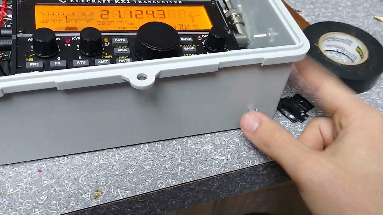
I went pretty sparse on the construction elements here. I wanted to mimic the design I saw featured on Radio-Set Go, but I lack 1. patience and 2. precision tools. I used spare polycarbonate and cut the square shape seen above. I drilled self-explanatory holes for the connectors as well, and drilled holes on the corner for 5M size screws with cap nuts and ring terminals.
I didn’t fix or mount the radio or tuner inside because it’s so tight that it won’t go anywhere. If I take supplies out, I may consider fixing with velcro or sheet metal as shown from Steve
Results
I haven’t taken the radio out yet, but I imagine it performs well. I had some initial errors with the type of audio jack that the MIC/PHONE/KEY ports take. Be very careful - they only take TRRS, TRS, and TRS respectively to function properly.
I have been monitoring the voltage and haven’t noticed a significant drop even with the arduino powering the real-time clock. I usually turn off aux power whenever the radio is not in use and switch to the CHG port just to be safe.
Further improvements
I may be running out of room to improve the case further, but there are some underused areas on the case. Maybe I can add a clipboard or some note-taking supplies to the top compartment, or add a quick expedient key in addition to the internal keyer. If I had an extra inch or two on the side, I may be able to camp out inside it on the summit.
Conclusion
This was a terrific weeklong SOTA upgrade. I can’t wait to take this out to the mighty 1-pointers of the Hudson Valley and eventually some much bigger summits in Colorado and the Catskills. If you have any improvements or suggestions, send them my way.
73 de N2WU