In preparation for the upcoming February 2022 West Point BalloonSat Launch, I improved upon last year’s SSTV Module to integrate actual flight pictures on the launch. With what may be the very first balloon module I’ve got working before the launch, here’s a detailed build guide and do-it-yourself instructions. As always, my code is available on github.
Operation
At a 100,000ft level (or 72,000ft, if you’re the BalloonSat team from last year), the device takes a picture, adds a timestamp with geospatial data, converts the image to an SSTV wav file, and plays the file on 2M. On a more picturesque view:
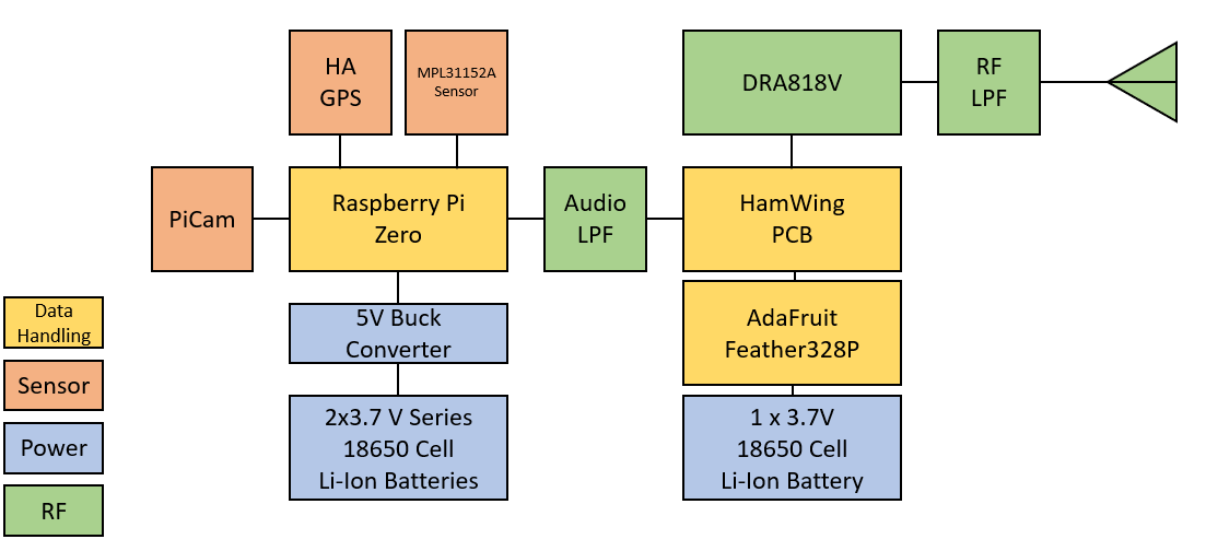
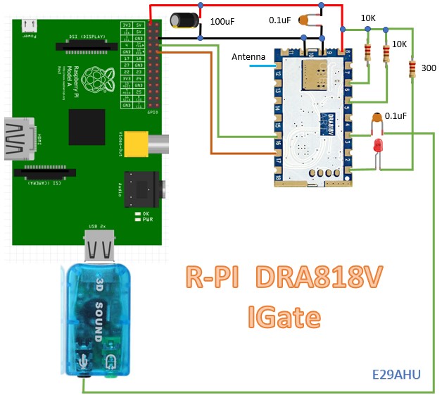
If you see, the coveted DRA818V Chip is used to modulate at our center frequency on the 2m ham band. I used W8LID’s HamWing Design to properly filter and easily interface with the chip, using a separate power supply and microcontroller.
I chose this design to keep my audio signal as clean as possible and eliminate timing confusion from an already overloaded Pi Zero. I let a microcontroller do all the work with the DRA818V because it 1) fit in the footprint, and 2) was too simple to need a microprocessor. However, my PTT commands and audio is still generated from the Pi as I’ll explain below.
I also chose to separate the power supplies just to isolate the radio and give it more current. The HamWing is only powered through the VBat JST connector on the Feather, so I needed power to go through there anyway at 3.7V.
Hardware
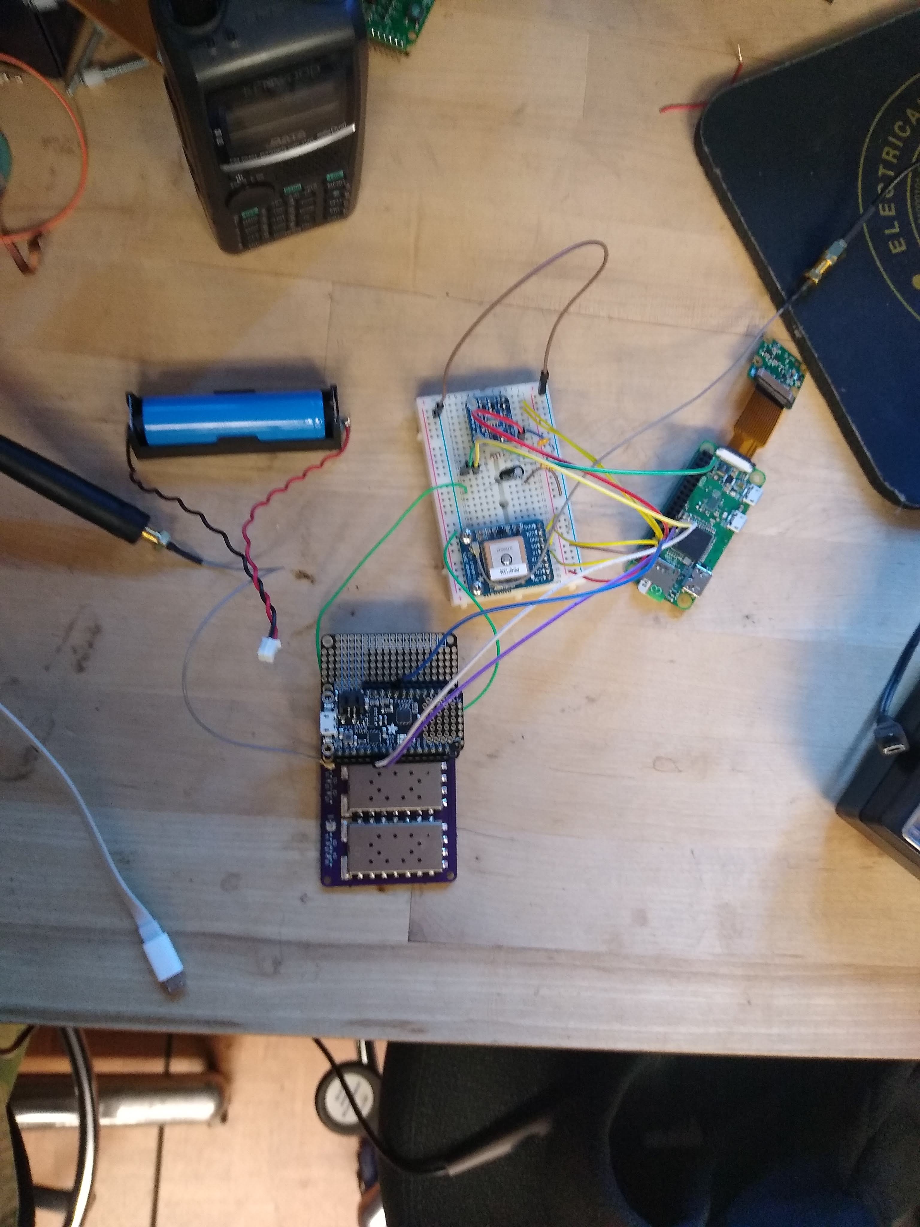
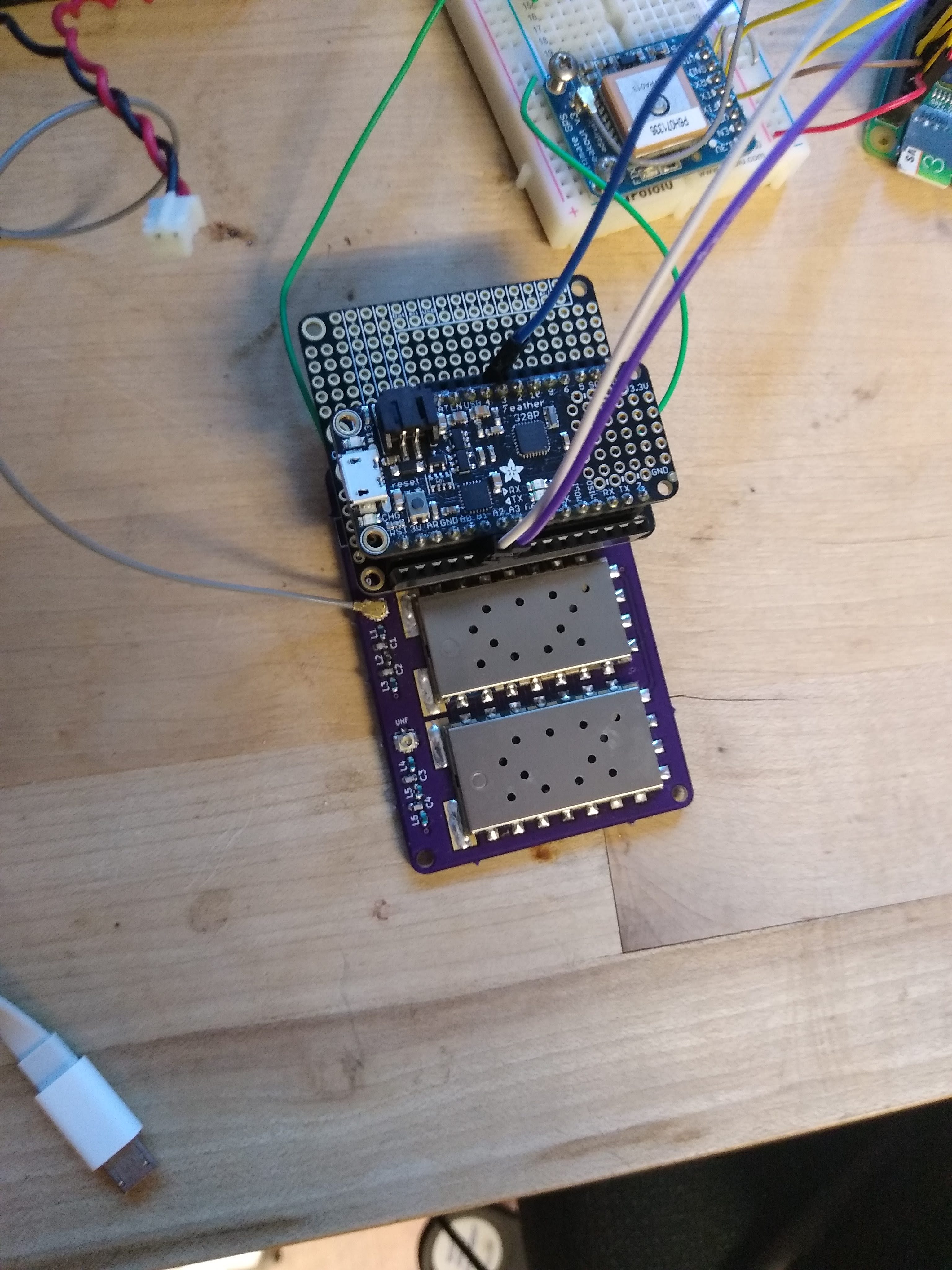
Full Breadboard:
This system requires a lot of hardware to work correctly. You will need:
- 3 18650 Cell Lithium-Ion Batteries. These things are indestructible, rechargeable, and reliable. I use these housings to create many different configurations in series and parallel to get my required voltage. For this project I had two in series for 7.4V to the pi system and one at 3.7V just for the radio module. In a future construction build, I’ll share just how easy it is to mount these in a payload box - easier than duct-taping phone chargers.
Actually, let me advise against using phone chargers as batteries quickly. You shouldn’t use “smart chargers” or anything not designed for PCBs. When the phone chargers get less than a specified current (like a sleep mode on a transceiver), they shut off. And you can’t wake it back up, or it will turn off again if you do. Use dumb chargers that get you voltage and current when you plug it in. It’s not terribly difficult to solder a USB-Micro connector anyway.
-
A 5V Buck Converter to step 7.4V down to 5V. Nothing fancy, but the Pi doesn’t like variations in voltage or current. Solder a USB-Micro Connector to this converter and plug that into the power jack on the Pi Zero. Powering through the GPIO is an accident waiting to happen.
-
A Raspberry Pi Zero W with headless SSH configured. Don’t waste time trying to plug in all the peripherals. Download PuTTy, WinSCP, connect the Pi to WiFi in the SD card boot options, and you can keep this thing outside with a gps fix while you are nice and warm inside.
-
High-Altitude GPS. Ensure you buy a high-altitude version; we use Byonics GPS5HA Module and it never fails. Ensure you have a model with TTL Logic, which are pins 3 and 6 in the GPS5HA module.
-
A PiCam with PI Zero Ribbon. You need the GPIO (and heat dissipation) so don’t bother with the case.
-
MPL3115A2 Temperature Sensor or another SDA/SCL weather instrument. This is “optional” but gives you usable data instead of just GPS coordinates.
-
A DRA818V Chip and antenna.
-
A populated HamWing Board or equivalent. I put together this order through Mouser, printed the board on OshPark and used SMD Soldering tools to get the components on. You need, at a minimum, some sort of filtering for the DRA818V and UART control. How you accomplish that is up to you.
-
An Adafruit Feather 238P or 3V3 Microcontroller. This is what the HamWing was designed for, so it’s what I chose.
-
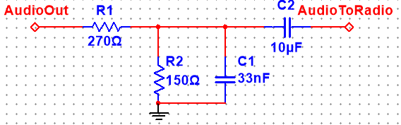
Some sort of Low-Pass Filter to fine-tune your audio source. Schematic below.
Raspberry Pi Zero
Congrats! You now have a pile of components. Here’s how to wire them up to the GPIO:
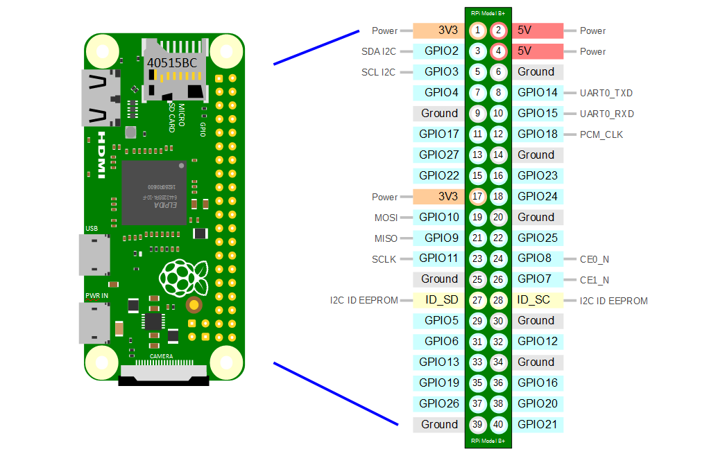
Full schematic here:

- Connect 5V to GPS 5V, assuming your GPS is 5V
- Connect all grounds together
- Connect GPS TX to UART RX (10)
- Connect GPS RX to UART TX (08)
- Connect Sensor SDA to Pi SDA (03)
- Connect Sensor SCL* to **Pi SCL (05)
- Connect sensor 3V3 to 3v3, assuming your board is 3v3
- Connect the PiCam via the ribbon
- Connect Audio Out GPIO 18 and 13 (Pins 12 and 33) both to the LPF input
- Connect GPIO 4, 27, 22 (pins 7,13,15) to HamWing PD, PTT, HL
- Connect LPF Out to your mic input on the DRA818V (or the Ring2 jack on the HamWing)
- Connect an antenna to the DRA818V
All set! Below is some more intermittent details on the hardware of the device.
GPS
For this application, I used UART to read and write the GPS. I used an Adafruit Ultimate GPS v3 with external antenna for breadboard tests but moved to the Byonics GPS5HA for the final version. Remember the TX of GPS goes to the RX of the Pi, and vice versa.
Also, remember GPSs consume high amounts of current. Ensure any long-running portable setups have the capacity to run.
MPL3115A2 Temperature / Pressure Sensor
I used the MPL3115A2 to get me a better reading on temperature and altitude for the device, but any telemetry SDA/SCL sensor will work. Just find an appropriate online library to read and format the data - don’t do any heavy lifting yourself.
PiCam
The PiCam is another standard module in any RPI toolkit. Use the ribbon cable and attach it on the opposite narrow side of the Pi Zero. Use the provided mounting holes and mount it to get a good view! I wouldn’t get a high-quality camera - remember, SSTV only transmits 320x256 images.
HamWing
If you can’t SMD Solder or can’t purchase a board, there are other solutions available. This guide from chokelive uses THT components:
However, I would add another BPF for 2M if you aren’t using the HamWing. They are incredibly noisy. Remember to cut your THT leads as short as possible to eliminate trace capacitance between parallel wires which could wreck an RF application.
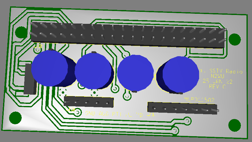
Here’s the HamWing in operation:
Adafruit Feather 328P
I used the Feather, but any UART microcontroller will do. I used a very basic script just to set up the radio commands as shown later. The feather has a built-in USB charging circuit for the LiPO as well.
I also built an Adafruit Doubler with extra female headers soldered on that would allow me to plug pins directly into the Feather.
I had the PD, PTT, and HL generated from the Raspberry Pi GPIO, which fed directly into the HamWing.
DRA818V
The DRA818V is used in just about every microtransmitter because of how easy it is to program and how small it is. Unfortunately, it’s incredibly noisy. Ensure you filter it somehow and provide adequate power. Read the manual just to make sure you program it correctly.
This board gets hot after SSTV transmission. I will be adding a headsink on the metal surface.
Software
Software is the key portion of this build. It took probably about 5 days of solid work to figure out what needed programmed where. Of course the final code sstv-new.py is available on github, but you need a fair amount of setup before you can execute.
This is assuming you have a fresh install of Bullseye from Rpi Imager. Using this you can directly add SSH and a wifi password with CTL-ALT-X.
Setup
First, you need all peripherals enabled in raspi-config. Boot up using SSH and type:
sudo raspi-config
From here, go to “interfaces” and enable Legacy Camera, SSH, I2C, and Serial. If you don’t see the Legacy Camera option, update your config.
GPS Setup
Good. Next, you need to install some dependencies. Follow these steps for GPSD, but wherever you see ‘ttyAMA0’, use ‘serial0’. You should be connected via UART on the GPIO which isn’t any more painful than using the USB.
Test if your device works by entering:
cgps -s
Pi Camera Setup
To use the PiCamera imaging with Pillow, use pip and these instructions.
SSTV Setup
I used this barebones GitHub library to quickly convert images to .wav. To execute download the recommended dependencies:
sudo apt install libgd-dev libmagic-dev
Then compile with:
make
That’s it! It needed an extra dependency on RPI than provided in the GitHub.
Audio Setup
Lastly, one of the more confusing steps was getting audio through the GPIO pins. I found this post was one out of 1000 to fix my issues. Execute the following:
sudo nano /boot/config.txt
Then add this to the bottom:
dtoverlay=audremap,enable_jack=on
Follow the instructions here for more details.
You should be setup now. I’ll step through the code below.
GPSD
I chose GPSD to elegantly access raw serial data. It takes a bit of setup but works well on python3.
# Connect to the local gpsd
gpsd.connect()

# Get gps position
packet = gpsd.get_current()
The actual positionData is simple:
def getPositionData():
    packet = gpsd.get_current()
    latlonString = packet.position()
    return latlonString
Many times I get varying errors due to “connection issues” with the GPS. This is fixed by running:
sudo gpsd /dev/serial0 -F /var/run/gpsd.sock
In the terminal or subprocess.call.
I2C and UART
I2C uses SDA/SCL and was a simple copy/paste.
def getWeatherData():
    bus = smbus.SMBus(1)
    bus.write_byte_data(0x60, 0x26, 0xB9)
    bus.write_byte_data(0x60, 0x13, 0x07)
    bus.write_byte_data(0x60, 0x26, 0xB9)
    time.sleep(1)
    data = bus.read_i2c_block_data(0x60, 0x00, 6)
    tHeight = ((data[1] * 65536) + (data[2] * 256) + (data[3] & 0xF0)) / 16
    temp = ((data[4] * 256) + (data[5] & 0xF0)) / 16
    altitude = tHeight / 16.0
    cTemp = temp / 16.0
    fTemp = cTemp * 1.8 + 32
    bus.write_byte_data(0x60, 0x26, 0x39)
    time.sleep(1)
    data = bus.read_i2c_block_data(0x60, 0x00, 4)
    pres = ((data[1] * 65536) + (data[2] * 256) + (data[3] & 0xF0)) / 16
    pressure = (pres / 4.0) / 1000.0
    presAltTemp = [pressure, altitude, cTemp]
    return presAltTemp
PiCam and Call Commands
PiCam uses the legacy module to take a picture:
with picamera.PiCamera() as camera:
    camera.resolution = (320,256) #as specified by sstv format
    camera.capture(completeFilePath)
    print("We have taken a picture.")
Then uses Pillow to “stamp the image”:
img = Image.open(completeFilePath)
draw = ImageDraw.Draw(img)
draw.text((0,0), newTimestampMessage, (255,255,255))
draw.text((0,20),timestamp2,(255,255,255))
draw.text((0,240),"CALLSIGN", (255,255,255)) #this is what makes it legal!
img.save(completeFilePath)
I was also cheap and used subprocess.call to run my commands:
- Name the picture
- convert it to sstv using ““/home/pi/pi-sstv/pi-sstv {} 22050”.format(completeFilePath)”
- rename the SSTV .wav so we don’t have several gigabytes of audio files
- Play
Writing to a CSV
While we’re at it, I wrote all the timestamped information into a csv using csv libraries.
def writeCSV(gpsData, weatherData, index):
    timenow = datetime.now()
    # Create file name for our picture
    stringTime = currentTime.strftime("%Y.%m.%d-%H%M%S")
    Row = [index, stringTime, gpsData[0], gpsData[1], weatherData[0], weatherData[1], weatherData[2]]
    with open(r'data.csv', 'a') as f:
Microcontroller and AT Commands
Like I said, I used the Adafruit Feather to relay commands to the DRA818V. I compiled an arduino INO to setup the AT commands.
Serial.print("AT+DMOSETGROUP="); // begin message
Serial.print(bw,1);
Serial.print(",");
Serial.print(ftx,4);
Serial.print(",");
Serial.print(frx,4);
Serial.print(",");
Serial.print(tx_ctcss);
Serial.print(",");
Serial.print(squ);
Serial.print(",");
Serial.println(rx_ctcss);
It’s not pretty, but it works for my purposes. I borrowed it from this source.
GPIO and aplay
I used GPIO for the High/Low DRA818V commands. Wire it up here:
DRA818_PTT = 27
DRA818_PD = 4
DRA818_HL = 22
GPIO.setup(DRA818_PTT, GPIO.OUT, initial=GPIO.HIGH)
GPIO.setup(DRA818_PD, GPIO.OUT, initial=GPIO.LOW)
GPIO.setup(DRA818_HL, GPIO.OUT, initial=GPIO.LOW) #High or Low power (Keep low)
Remember that HL is Low (0.5W) or Float (1W). Never High!
My audio streams out on GPIO 13 and 19. It doesn’t work with one or the other, but tying them together works fine for mono.
This command plays the audio:
aplay /home/pi/timestamped_pics/sstv.wav
Tests and Improvements
Initial tests were pretty successful. The picture was just the PiCam laying face down on a desk:
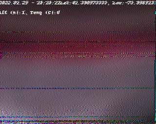
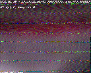
The little blips of noise on the test image is from an irritating, looping pi version of sticky keys. If you have that, disable it here.
We used 0.5W and received it clear throughout our entire building. I will add text enlargements and an image number in the future. I’ll also make my callsign bigger.
Since the pinout was rather hard, I made a gerber zip for a simple daughterboard here.
Conclusion
I can’t wait to get this thing on the payload. It needs a little more fine tuning but will be more than successful at 100,000 feet.
-N2WU