DIY Spinning LED Nightlight Circuit
After delays at the post office hindered any chance I had of completing projects, I finally built a 3-stage spinning nightlight circuit! It’s the perfect gift for Valentine’s Day. Everything your partner needs - a voltage buffer, 555 timer, and decade counter.

The perfect gift!
This project had several stages and kept me busy over January. It only operates in darkness and sequentially lights up 10 LEDs. Chiefly, it contains:
- Voltage Buffer / Common Source Nightlight Circuit
- Clock Circuit using an LM555
- Decade Counter using an IC4017
- Prototype
- Printed Circuit Board
- 3D Printed Assembly
Overview
I wanted this project to be low power, low weight, and operating at very specific (but automatic) conditions. I decided on the nightlight because it was just another step to make the circuit cooler. Similarly, the spinning effect looks cooler than standard LEDs. “Cool” will soon be an academic term.
The biggest problem in this circuit is current management. LEDs consume a lot of current, but using a photoresistor with a large resistance (about 2.3 M Ohm) and the impedance of the ICs severely limits how much current the LEDs can take. For this reason, I went with the voltage buffer circuit. I chose the clock circuit because of the simplicity of the astable 555 timer, and chose the decade counter since it would be the easiest to power 10 sequential outputs.
The best answer is usually the easiest, right? Below is the schematic for the full circuit. In the simulation, I used a SPDT switch with two resistors (100 and 1M Ohm) to act as my photoresistor. More explained on the theory later.

Full Schematic
Voltage Reference/ Nightlight
Photoresistor Basics
The photoresistor is the key to this nightlight circuit. The photoresistor is a passive device that has low resistance when in ambient light, and extremely high resistance when in darkness or low light. I found my device (specifically the GL5516) had about 2.3k Ohm in light (all lights on in a room) and 3.5M Ohm in darkness with lights off. I built my circuit reliant on these changing resistances.
Common-Source Configuration
I used a common source MOSFET to drive the entire circuit. I wanted something that would react well with the high resistance. I took inspiration after a lab I completed in my microelectronics class:
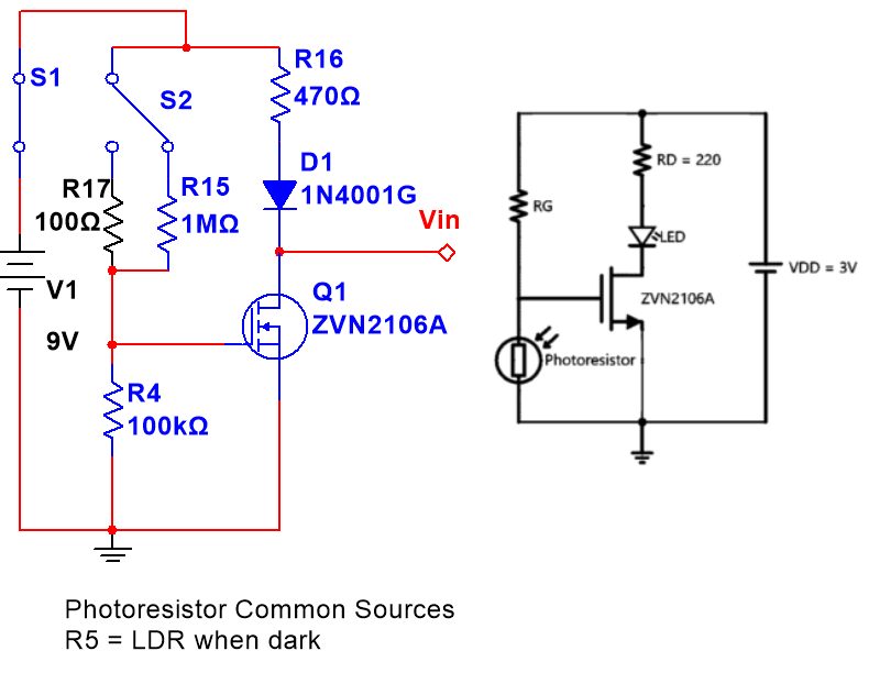
Left: Photoresistor Circuit in Design, LDR = R15. Right: “Night Light” Circuit from class
If you examine the two designs, you will see I have an increased voltage (9V from 3V), I switched RG and the photoresistor (LDR), and that the LED is substituted for the 1N4001G. However, I kept the common-source configuration and the current-controlling resistor for the diode.
Circuit Operation
I find it really important to know why my circuit works how it does. That way I am not scrapping for answers if I need to solve problems quickly. We can begin by tracing the voltage through the entire circuit, first in presence of ambient light (circuit is “off”). The transistor is governed by the central MOSFET equations below:

The 9V from the battery reaches the first junction. Due to the voltage divider equation, Vth = Vcc * (R2)/(R1+R2) , the Thevenin voltage at the drain would be 8.99 V. This is greater than the datasheet value for Vtn of 0.8V. Even though the circuit is not in cut-off, the voltage at the diode is lower than the forward voltage value (datasheet says 930 mV, but I found it almost exactly 680 mV), so no voltage is provided to the drain. Since no voltage is provided to the drain, the transistor is in Triode operation and less-than-operational voltage (about 25. mV) is delivered to the ICs.
When the circuit is on, R1 is extremely high. The Thevenin voltage is about 825 mV, just over the threshold voltage. The transistor is turned on, and since the voltage at the diode is higher than the forward voltage, current can flow across it. Vds is higher than Vgs - Vtn (close to 0), so the transistor is biased in the saturation region. This delivers the needed 5V to the rest of the circuit!
I was not extremely selective on resistor values here. Both chips have a range of Vin from 5-8V. I knew I needed to select R1 (the 100k resistor) to make Vgs > Vtn. The current-limiting resistor really just limits current.
Clock Circuit
I borrowed instructions on 555 setup from the link here which achieves my same end state. The clock duration is calculated through the capacitor and resistor values by the equations below (from this website):

Resistance in Ohms and Capacitance in Farads
Using these equations, I get a time period of about 0.067 seconds, which makes the LEDs move at a brisk (but watchable) pace. Below is my 555 circuit, where pin 3 goes directly to the “Clock” line of the decade counter:
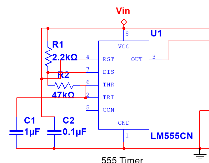
555 Circuit
Decade Counter / LED Circuit
This was the easiest part of the circuit. I followed the same link above and connected 10 LEDs in-line with the output pins. I left the “~Q5-9” pin as a Don’t Care because I am only using 10 LEDs. I also added current-limiting resistors to the LEDs since simulations gave me “roughly Kiloamps “ without them. I used this equation (found here) to determine the ballpark estimate for my resistors:

LED Resistor equation from KVL and Ohm’s Law
I found a value of about 40 Ohms with a supply voltage of 5V, forward voltage of 2V, and max current of about 500mA. I bumped this up to 51 Ohms for security and to meet a standard value.

Decade Counter
Prototype
I breadboarded the circuit and everything matched up well. This is the most important step really - it took 5 revisions to get to a correct version just on the breadboard. The IC circuits presented a nonzero impedance to the photoresistor circuit, so I had to account for it with the common source voltage buffer. I was able to get the breadboarded simulation below (excuse the classical piano):
https://youtu.be/SnW43sKjXOA
Printed Circuit Board
The section requiring the most engineering was the PCB printing. I used Ultiboard, drew in all the traces by hand, and substituted my switch configuration for the photoresistor for a single resistor (R5). I was also able to arrange the LEDs in a heart shape. I made the circuit bottom-heavy since it will be mounted near vertically. Additionally, I used a ground plane to make connections much easier. Using the ground plane reduced complications with the circuit, so I was able to print it just as a one-sided board and use wires on the top side. To check my solder connections for bridges, I used a multimeter on the diode setting - if there was no forward voltage found (with a loud beep to accompany!) I resoldered or scratched some solder off with a razor.

3D Render of PCB
3D Printed Enclosure
I outsourced this project to some friends much more competent in 3D design. I wanted the board mounted near-vertical with a place to hold the voltage source (a 9V battery). The simplest way to do this was a 60 degree incline and a flat “tray” secured with zipties for the battery. Here’s a better look:

Demonstration
Here’s the working demo! It works in any room with lights off - not perfect darkness, but not too much brightness either. The circuit has low current consumption when not actively spinning. Also, I had to change R2 to 470 Ohms instead of 220 to account for red LEDs instead of yellow from the breadboard. The standoffs are standard 4-40 size.
https://www.youtube.com/watch?v=ZNA89MwXq-Y&feature=youtu.be
Hope you all enjoyed! If you want the gerber file or any specifications please ask!