Phase Synchronization for Ettus X310
I recently have been experimenting with the time-synched Ettus X310 for beamsteering and MIMO research. However, the device receives both signals with an intrinsic phase offset that requires syncing and calibration - something I fixed with a GNURadio script. I share my theory and code below.

Finished Flowgraph

Full Flowgraph
The function below takes in two USRP signals (from a SBX board in this case) and calibrates both the magnitude and phase of the 2nd signal. It uses a “Function Probe” block to find the approximate frequency (get_freq) and phase delay (get_phase) of the signals. It then uses a time delay and an amplitude amplification algorithm to “calibrate” the second signal. Because of the delay block, the algorithim can calibrate accurate phases +/- 180 degrees resulting in the output below:
Amplitude Calibration
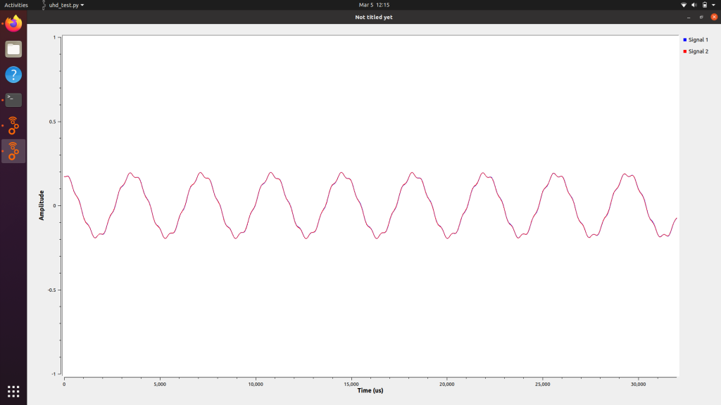
I created a half-wavelength uniform linear array with two elements from the X310 but received the following initial output from an ordinary oblique angle:

Attenuation on 2nd Signal
The amplitude of the signal here, though calibrated, is much more attenuated than the first blue signal. Even with uniform gain, this output still occurs. Rather than fix it, I corrected the output to match amplitudes through amplification:

Amplitude Magnification
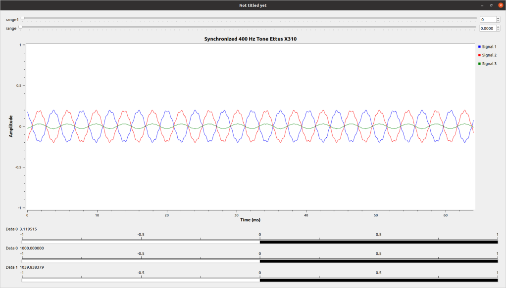
This section measures the two magnitudes of the exponential form of the signal, then finds the ratio between them. This constant is then multiplied by the original magnitude of the signal to make it equal to the magnitude of the 1st signal. Matching these amplitudes results in a calibrated setup:
Synced Signals
Phase Calibration
The ettus, according to this link, often has a random phase offset due to timing differences. Any time or phase-delay signal manipulation (like MUSIC, psuedo doppler, or beamsteering) requires a time- and phase-synced signal. My code needed to identify this phase shift and implement it via a time delay. Although I was using GNURadio 3.9.0, my “phase shift” block failed to load.
My first step was to calculate a phase difference between the signal. For this, I took the phase of the complex exponential form of the signal using these blocks:
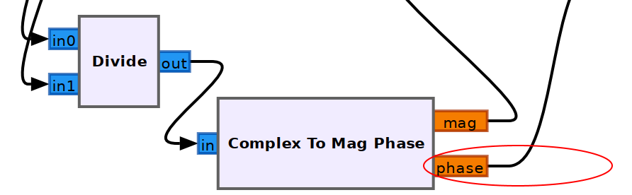
Phasor Division
From Signals and Systems, a complex signal has the following form:

If the two signals are divided, the following phase shift occurs:
x1(t) = Ce^at
x2(t) = Ce^at
x3(t) = x1(t)/x2(t)
x3(t) = (C1/C2)e^t(a1-a2)
The (a1-a2) term is my phase shift relative to a noncomplex signal - a sine wave. I take this phase shift and multiply it by a constant to turn it into an amount of samples to delay my signal. I found this value to be 1000/3 through qualitative analysis; I have little reason for this inference.
Experimental Setup
I used a signal vector generator and my Ettus X310 to receive two signals. I created a 400 Hz tone modulated via AM modulation on 466 MHz transmitted to the Ettus via dipole antennas on all elements; this result in a highly attenuated and unstable signal. Instead, I used a BNC splitter and connected the generator directly to the source.
Conclusion
The most time-consuming step in phased array applications is phase sync. I hope with this script I will be able to calibrate slightly more effectively than before, and be able to implement time-delay beamforming in some of my next experiments.
I plan on implementing this to Coherent RTL-SDR receivers when possible for an economic solution. Also, I experience limitations from my test from using a basic AM signal as the calibration source - I have to figure out a robust way to calibrate using either a more complex signal or a better process for calibration and switching.
Code available here.