DIY Class-A Audio Amplifier
Recently as a final project for one of my electrical engineering classes, I build a class-A amplifier using two bipolar-junction transistors (BJTs). The circuit had a lot of interesting quirks and design considerations, so I wanted to post it below.
Amplification up to 11!
Circuit Design
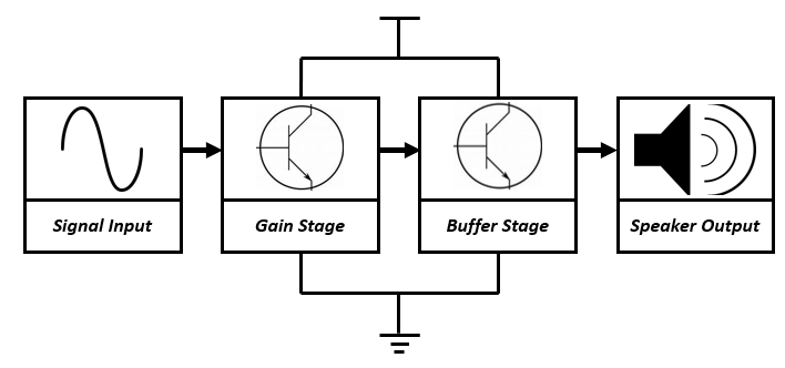
Typical audio amplifiers usually have two stages - a gain phase and a buffer phase. This is because of the audio part in the audio amplifier. The output of the circuit, a speaker, has very little resistance - about 8 ohms. So if you amplify any signal, it will most likely not make it to the speaker because of the large characteristic resistance of your gain circuit. The buffer stage fixes this - it is also called a resistance transformer for this very reason. It makes the characteristic resistance of the gain circuit comparable to the output - the extremely low 8 ohms from the speaker. Below is a simplified diagram of what it would look like:
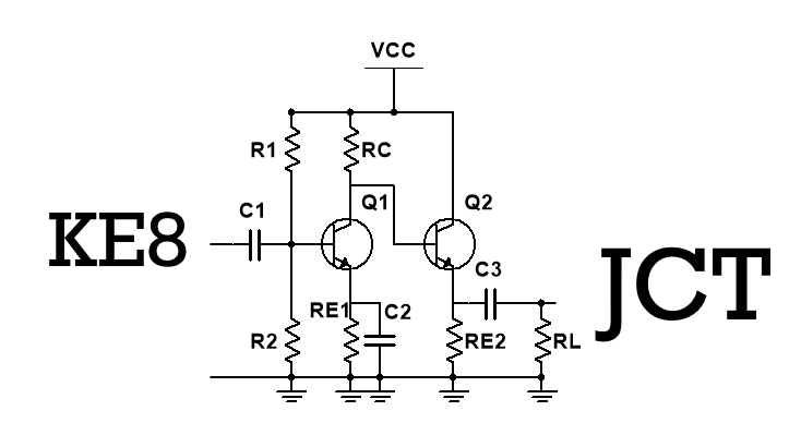
This circuit can be constructed in any number of ways. I found most of my classmates used a BJT for the gain stage and a metal-oxide semiconductor field-effect transistor (MOSFET) for the buffer stage. I actually opted to use two BJTs instead - there were less circuit components and less confusion over what analysis methods to use. Our finished circuit looked like this:

Finished Simplified Circuit
Important here are the presence of capacitors. These capacitors have different characteristics in AC and DC mode. When in DC, the capacitors are assumed to be open circuits. When in AC, the capacitors are assumed to be short circuits - meaning RE1 is negated in AC analysis but valid in DC analysis.
We aimed for an absolute gain of 20, or a gain of 26 dB. This circuit and associated MATLAB calculations gave us about 25.6 dB. We changed the resistor values to get achieved gain, mainly R1 and R2 after selection of RE1,RE2, and RC. We found optimal ranges for those three resistors that had to match the load resistance RL.
The small-signal analysis for the circuit looks like this:

Simulation
We loaded our circuit design into multisim and compared the values. We first had a widely different gain than expected, but later learned this error was due to an incorrect beta and Early Voltage value - two characteristic values that change for each transistor. After taking data from actual transistors in our lab, we found widely different Early voltages and beta values. We used this resource to accurately find those values - MATLAB was used to perform the analysis.


After we ported our values into multisim, our circuit looked like the one below. We included the measured resistance from our lab - so a 66.79k Ohm Resistor would be an unideal 68 kOhm one. The capacitor values varied widely from their ideal values, but C1 is a 10 uF and C2/C3 are both 100uF electrolytic capacitors. R1, the source impedance, is not an actual resistor. It is merely the input impedance of the function generator (50 or 75 ohms).

Results
Our constructed circuit performed well. Below is the oscilloscope output for our signals. The blue is our input signal, green is the gain after the first transistor, and yellow is the final gain:

Oscilloscope Output for the 2-stage circuit
We noticed initially that our values were nothing close to the simulated values. We learned this was because we failed to account for the high power in the system - a simple change to a high-power BJT (the TIP41a) and 5W resistors fixed this issue.
Conclusion
This was a fun and rewarding project that allowed us to explore and customize the function of transistors. Through a lot of trial-and-error we learned the right resistor choice and how a high-power signal like the one produced performs in our circuit. We had very little distortion when listening to our signal so it was ultimately a success.
Here are some error percentages for the circuit:

High Gain, low percent Error!
Extension: Power supply
We also used four diodes and made an AC power supply into the circuit. It was just one more extension and taught us about turn-on voltages for the circuit. Here is what it looked like in our circuit:

AC Transformer
This project was a lot of fun, but inefficient. Class-A amplifiers are extremely wasteful, so a smarter choice of amplifier would lead to greater power conservation.
Stay tuned for some upcoming winter break projects! As soon as the post office delivers it…