Voltage Regulator and DC Loading
I recently built my voltage regulator circuit mentioned in some previous posts. While building it, I learned some important lessons regarding DC loading I hope to share below.

Don’t Try this at Home!
Theory
My circuit uses the LM338 and LM117 / 317 to scale 24V in down to 16.8V, then 9V. This circuit is for a lithium ion battery charger. As per my multiple previous posts, the battery I am dealing with is a Conformable Wearable Battery (CWB), a 16-cell 5A max galoot. My circuit aims to 1. charge the battery with 16.8V in and 2. power a display circuit at 9V.
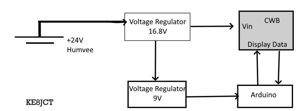
The main problems to this circuit include loading. A load is the device that uses the voltage in my circuit. Here, it is the arduino / battery combination. This circuit is especially complex, as the arduino has an onboard voltage/current regulator and accepts any input from 9-12V. Similarly, the battery has a capacity of 16.8V able to be discharged while charging.
Some engineering considerations I made were the transient response of the circuit. I included some diodes and capacitors to bleed current. If there was a large surge in current (as I expect in my specific application), I want the circuit to be protected. Below is a snapshot of my simulated transient response; it bleeds off excess voltage.
![]()
Construction: 16.8V Regulator
The 16.8V Regulator gave me virtually no issues. I used the steel LM338, so I tried to keep other circuit elements away from its unwieldy size on the breadboard. Here is a schematic of what I tried to build:

I standardized my resistor values by approximating available resistors in series. I had this as my final breadboard design:
The voltage was measured across the 1 uF capacitor, like a load in parallel. The system seemed stable with no excess heat across the voltage regulator and no shorting of capacitors/diodes.
9V Regulator
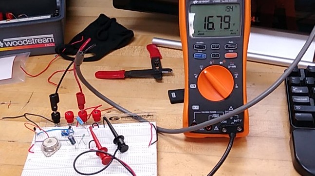
The 9V regulator follows the same design but with different values for R1 and R2. Rather than step down 24V to 9V, I stepped down my previous 16.8V to 9V. Below is what the completed circuit looks like, with an output reasonably approximate at 9V.


After this, I connected my load. The load was an Arduino Uno and LCD screen. When I connected it, the output voltage immediately dropped to 1.261V and would not change regardless of R1/R2 value. The load circuit has a large resistance relative to the charging circuit, an issue I would see described later. Eventually, I found an accurate R1 value to be 70 ohms and an R2 value (on bottom) to be about 240 Omhs.
Load Issues / Analysis
As previously mentioned, my load voltage was not working properly when I initially tested my circuit. I fixed this by changing R1 and R2 values to be smaller than the load. To find the internal resistance of either circuit, I used this diagram, a potentiometer, and a voltmeter.

I found the internal resistance of the charging circuit to be nearly 1.183 Mega Ohms! Astoundingly high. Similarly, when connecting to the battery circuit, I found the internal resistance to be about 40 Ohms. This difference has massive effects on my circuit.
Lastly, after finally achieving a successful connection and powering of the arduino, my output voltage read 5.415 V. I imagine my 9V input regulated to the logic level of the arduino, 5V.
Application
The last step of my project included actually charging the circuit. However, my previous design failed and I was unable to actually read charge data from the device. I will have to revisit interfacing with the battery over I2C, but the completed breadboard design looked like this:

Neat, organized breadboard test
Conclusion
In this exercise I finally tested my successful charging circuit. I encountered a problem with my DC load but was able to resolve it by finding the internal resistance of the equipment and reducing my input load. Although I was unable to get successful charge data, I was able to correctly build the voltage regulator circuit.
My next steps include streamlining the data acquisition of the battery, charging it with the 16.8V line, performing current tests on the circuit to see how many amps it will take, then printing a circuit board and having a finished product.