Transient Response and Simulation with NI Voltage Regulators

Voltage regulators are commonly used to step down DC voltage to a lower output at a constant current rating. In this study, two voltage regulators - the LM117 and LM338 - are simulated in both a simplified and advanced output model within MULTISIM. The transient response is measured and safety considerations are implemented with forward-biased diodes to prevent backwards flow of current.
Background
Voltage regulators are small circuit components capable of easily maintaining a constant voltage level. They can change AC/DC and step up/down voltage levels, with some devices capable of constant current. For this study, only two devices were analyzed: the national instruments LM117 and LM338. These devices were chosen for their application and part in a larger project explained below. Voltage regulators are often used in li-ion battery charging circuits for their constant voltage, constant current ability.
Due to the simplicity and utility of the devices, often fine-scale spurious current becomes an issue in the circuit. For this reason, linear charging circuits often have capacitors and diodes to bleed excess current and restrict flow to a certain direction. If the voltage source of a voltage regulator often turns on and off, excess stored current could be harmful to the powered device. The analyzed circuits use datasheets [1] and [2] ‘s given diode protected circuit. Shown below for [2], the circuit utilizes many electrolytic capacitors to obtain a smooth, controlled voltage for the circuit.
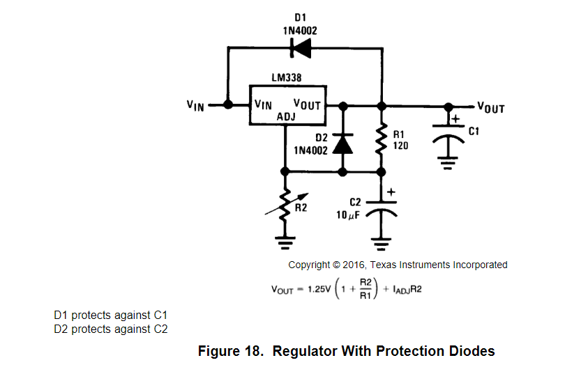
Both voltage regulators used in the study have 3 pins; V_in, V_out, and ADJ. The circuit uses two resistors in a voltage divider to maintain a correct output voltage. The following equation shows how output voltage is calcualted:

V_out for a voltage regulator circuit.
Where R1 and R2 are resistors, and I_adj is the current through the adj pin of the voltage regulator. The study found I_adj to be nominally 0 through testing.
Although the circuit is safer than a bare LM338, problems still occur with efficiency. The circuit has a transient response; meaning, after the circuit is powered, the device still takes some time to fully output its voltage. The transient response is measured and explained later in the paper.
Application
Vehicles output a constant 24V, but are subject to intense current surges upon vehicle start-up. In addition, no voltage regulators or conventional power sockets exist in a vehicle; any device must be stepped down with proprietary equipment. The use of voltage regulators allow for greater customization and a smaller footprint in non-24VDC usage.
This circuit aims to power two devices; one, a lithium-ion battery to charge. Second, a microcontroller (specifically an Arduino Uno) to control the device’s charge via SMBus, a well-known serial interface for lithium-ion batteries [4].
Therefore, two voltage regulators were picked. [1] is the LM117, a regulator at 9V and 1.5A; an ideal operating voltage for the Arduino Uno [5]. [2] is the LM338, a device operational at 16.8V and 5A; ideal for the 16-cell lithium-ion battery.
Experiment
Two circuits were constructed on Multisim using Figure 17 in [1] and Figure 18 in [2]. The multisim component for an LM338 was obtained from [3]. The initial constructed circuits are labeled below.

LM338 for 16.8V

_9V for LM11_7
First, each circuit was tuned with a potentiometer to measure R2. With the multimeter under “V_out,” the potentiometer was incremented linearly until the desired voltage was reached within 10%. Then, the value was substituted with series resistors and a 100-ohm potentiometer for more accurate tuning. The study found R2 = 1486 ohms for LM338, and R2 = 1470 ohms for LM117.
Theoretically V_out is calculated below for 9v and 16.8V


The actual circuits have a percent error of .456% for 1) and 1.21% for 2), respectively.
Results
Measurements
The data for each circuit is shown below. A multimeter in place of the V_out sink was used to measure V_out voltage. A current probe in multisim was placed across the ADJ connection to measure I_adj, which was found to be nominal.

Measured Values for LM338.

Measured Values for LM117.
In addition, the final circuit will have both elements powered off of the same 24V line. Results found that a series configuration (powering the 9V line off of the 16.8V V_out) kept the same ideal voltage levels. This makes sense because the equation of V_out is independent of input voltage.
Transient Response
While incrementing the potentiomenter, accurate voltage levels took upwards of 2 seconds to be reached. With a completed circuit, the transient response was measured. The circuit took upwards of 500ms to reach a stable voltage. This is beneficial to a constant on-off source; quick knife-edge changes could result in spurious current surges into the sinks.
![]()
Transient Response for 500ms
![]()
Transient Response for 100 ms.
The voltage reached a peak at 16.8027 V, which can still be considered nominal in the charging circuit.
Extension / Conclusion
Two diode-protected voltage regulator circuits were simulated on multisim for 9V and 16.8 output voltages. The value of R2 was found both experimentally and theoretically with a small percent error in both cases. Further, the transient response of the electrolytic capacitors was found and determined to be suitable for unstable power supplies.
Extensions of the project can more safety measures to the battery charging circuit. Current cut-offs have been mentioned in [6] using a BJT Transistor. Finally, novel methods could implement wireless charging or other contact methods outside the scope of this circuit’s design. This design could also be physically realized for further confirmation of the theory behind voltage regulators.
Sources
[1]. National Instruments. LM117, LM317-N Wide Temperature Three-Pin Adjustable Regulator datasheet (Rev. Q). June 2020. https://www.ti.com/lit/ds/symlink/lm117.pdf
[2]. National Instruments. LM138 and LM338 5-Amp Adjustable Regulators. May 2016. https://www.ti.com/lit/ds/symlink/lm338.pdf
[3]. User “konradIc13.” “Problem with voltage regulator lm338.” November 19, 2013. https://www.electro-tech-online.com/threads/problem-with-voltage-regulator-lm338.138952/
[4]. Duracell et. al. System Management Bus (SMBus) Specification. August 3, 2000. http://smbus.org/specs/smbus20.pdf
[5]. “Arduino Uno Rev3.” Arduino. 2020. https://store.arduino.cc/usa/arduino-uno-rev3
[6]. User “Swatagram.” “4 Simple Li-ion charger circuits.” June 15, 2020. https://www.homemade-circuits.com/simplest-safest-li-ion-battery-charger/