Arduino LCD Battery Display
Not a radio project for once! Maybe I can do more than just RF.

Out of place…
Recently I made an arduino-controlled LCD screen that displays voltage and charge on a connected lithium-ion battery. Below I explain how I did it.

Needs more wires
Background
As usual I didn’t actually write anything, I just cobbled together various other working arduino scripts.
First, the battery accepts SMBus commands. Here is the current SMBus protocol. It relies off of microprocessor commands and addresses to read data. For this project we are concerned with voltage (0x09) and StateOfCharge (0x0d).
Dan Milliken provided me with a very useful script to read the battery’s charge and voltage from the serial monitor. I posted my (his) code down below.
The LCD had to be configured to display our information. I used only digital pins and used an LCD with model number #LMB162ABC and this website to connect all the pins. I used 50 Ohm resistors wherever a resistor is mentioned and it turns out fine. Everything connects to an Arduino Uno with 5V operation.
Lastly, the LCD relies on a graph to display its charge as a percentage of the whole screen. I found this article on the arduino forum and it works very nicely. It takes the StateOfCharge variable and displays it as a percent from 0 to 100. Huge thanks to forum user Davide_Asnaghi for creating it.
Setup
Reading I2C information requires a pullup resistor on this device. This way, the device is an active-low triggered device. I used two 4.7k Ohm resistors as shown below and had no problems. You’ll find a lot of projects use this value, but if your i2c device operates at 3.3V you will need a different configuration.
I found my battery’s datasheet for the location of its pins. You only need GND (CHG- here), CLK, and DAT to send/receive information over i2c. It is important to note that A4 is the data pin for the Wire.h library, and A5 the clock. These can be used interchangeably with SDA and SCL on the other side of the arduino, but must be used as a pair.
Double check your CLK and DAT wiring beforehand! I burned quite a few arduinos by mixing up the two.

Schematic
Code
Here is a link to my code on github. I included the standard read script and an option for 7 segment displays. Below I’ll highlight the important parts.
Here, you’ll want to define your LCD by the pins you connected. Reference the aforementioned website for how I set mine up.
#include <LiquidCrystal.h>

LiquidCrystal lcd(12, 11, 10, 5, 4, 3, 2);
Next, you need to “query” the battery using Wire.h . You are querying it at a specified address. For most batteries you will use 0x0b, or 11.
double getvoltage()
{
  Wire.beginTransmission(bl03_address);
And here’s the loop that connects it all. If a new charge percentage is detected, the lcd will update. It uses the “setCursor” function to figure out where to write specific information.
if(currentSOC != newSOC || true)
  {
    currentSOC = newSOC;

    Serial.println("Battery Info");
    Serial.println("------------------------");

    Serial.print("SOC: ");
    Serial.print(currentSOC);
    Serial.println("%");

    Serial.print("Voltage: ");
    Serial.println(getvoltage());
    LCD_progress_bar(2, currentSOC, 0, 100);
    lcd.setCursor(0,0);
    lcd.print(getvoltage());
    lcd.print("V , ");
    lcd.print(currentSOC);
    lcd.print(" % ");
    delay(500);
    Serial.println();
    Serial.println();
  }
The “LCD Progress Bar” requires a row number(I used row 2 on a 16 x 2 LCD), value, and range:
void LCD_progress_bar (int row, int var, int minVal, int maxVal)
Results
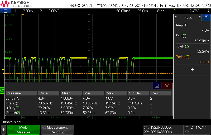
It works! There isn’t much more to say. Without the battery connected, the device displays a nominal voltage of about 3 volts and a 3% charge. I might display a “splash screen” of sorts to prevent confusion on the battery’s connection in a future update. Below is the waveform for reading i2C data, with an oscilloscope connected to GND, CLK (green) and DAT (yellow):
Conclusion
This project took quite a while to “complete” - about 4 months. My biggest hurdle was physically connecting to the battery, as it had flat copper pins on the bottom. I decided to use alligator clips on a repurposed connection cable instead, but will soon find other ways to connect. After I figured out the connection I finished in about 2 days.
In the future I will over-engineer this project. I will create a custom PCB to eliminate some of the jungle of wires and make it durable. However, I’ve never had a project make it past the prototype stage so I’m excited to see where it leads.