Modeling Matches on EZNEC Demo
Recently I have been using EZNEC Demo to simulate some of my favorite antennas. However, my favorite antennas include more than a dipole. In this post I will show you how to use transmission loads to model different types of matches on EZNEC.
Fair warning, I am very unqualified on this. I got my niche project to work but your mileage may vary.

A few of my favorite antennas
Background
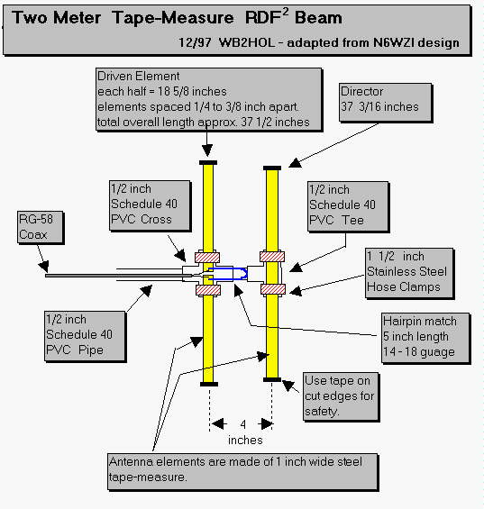
For this project I am primarily referencing Joe Leggio’s RDF2 Tape Measure Antenna. I have already built his 3-element and a couple others, but you will have to wait until Southeastcon for that. I am using the EZNEC program referenced above. My goal in an experiment was to computer simulate, then design, several directional antennas and test their field performance for the past foxhunt we did.
Non-Math Theory

I may be stretching the truth…
Our antenna has more than one element. The current from the coaxial cable is only connected to one beam, the director or driven element, while the other (the reflector) actually reflects the beam into the connected element. However, it gets a little more complicated than that. Take a look at the underside of the tape measure antenna:
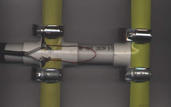
Director (left) and Reflector (right)
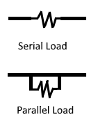
Turns out, the driven element actually isn’t connected all the way through. The current from the coax goes in one element, and the ground on the other side. There is a 5-inch hairpin match that connects this: if you connected both current and ground to a single tape measure, your wire would short. This wire allows for tuning and better standing wave ratio (SWR) for the antenna. This wire carries an impedance that adds a load to the antenna. It has an ohmic value that opposes flow of current. This load connects to each end of the antenna, so it runs in serial. Below is a quick drawing of the difference between a serial and parallel load.
Another less-than-obvious fact to this antenna is the angle of the coax cable. The cable must be perpendicular to the elements; anything other perpendicular results in terrible SWR. I used zip ties to secure it.
Modeling on EZNEC
EZNEC Demo is a computer program. That’s about all I can say about it in good faith. Eventually I got somewhat of a grasp on it, but I would recommend constructing a dipole to gain familiarity with the program. After that, you know where the buttons are, so pick from the pre-built examples and scale it to the frequency you want.

2-element Yagi modeled on EZNEC
Constructing the wire segments for this antenna was a breeze. I used the handy construction manual from the antenna engineer’s website and placed my segments along the x axis. You will have to use inches as your measurement. For the Driven element, I used the total overall length instead of 2 separate antennas; I will show you the magic behind this later.
Below is my “wires” tab on EZNEC. I divided my total length in 2 to place the center of each antenna along the x axis, so it goes from (-value) to (+value).
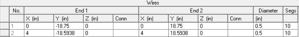
All antennas need a source, right? So input a source directly in the middle of the driven element, current based:

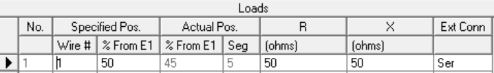
Lastly, the magic happens. You will need a serial load to act as the hairpin match in the picture of the antenna. It carries a resistance of 50 ohms (my feedline) and reactance of 50 ohms. I cannot tell you in good conscience where I got these measurements from, so let me know if you have any idea why.
Antenna Theory is an approximate science.
And that’s a wrap! Fire up the SWR graph and FF plots!
Results
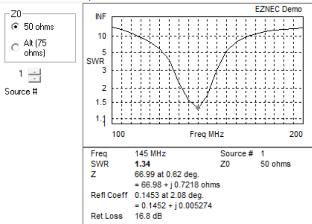
Here is my SWR for the simulated antenna, from 100 to 200 MHz. The antenna should be resonant on 146.565 as stated in the construction manual, however it still is tunable via the hose clamps on the PVC pipe.

SWR of 1.28:1 on 145Mhz!
Possibly changing the resistance and reactance values on Loads will affect this measurement. Only time (and actual theoretical knowledge instead of button-pushing) will tell.
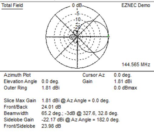
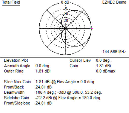
Here is the far-field azimuth and elevation plot, with the antenna pointed at 0 degrees:
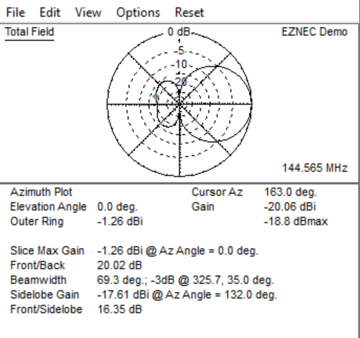
Azimuth
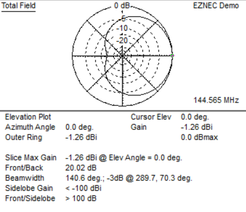
Elevation
Overall, I achieved a SWR of 1.28:1 on 145MHz, with wide but directional lobes. I had a front-to-back ratio of near 20dB! Which of course will get lost with LEDs outside…
With the 3-element Yagi, you sacrifice boom length for nominal gain (24dB). The resonant frequency stays at 145 MHz, but increases to 1.34:1. Here is the SWR and far-field plots:
VSWR, Azimuth, and Elevation for 3-element tape measure (oriented towards 0 degrees)
Conclusion
This took a lot of work to complete. I’m sure other antenna modeling programs could measure this slightly easier, but this program is free and used by hams. Below is the actual VSWR measured with a FieldFox Network and Spectrum Analyzer:
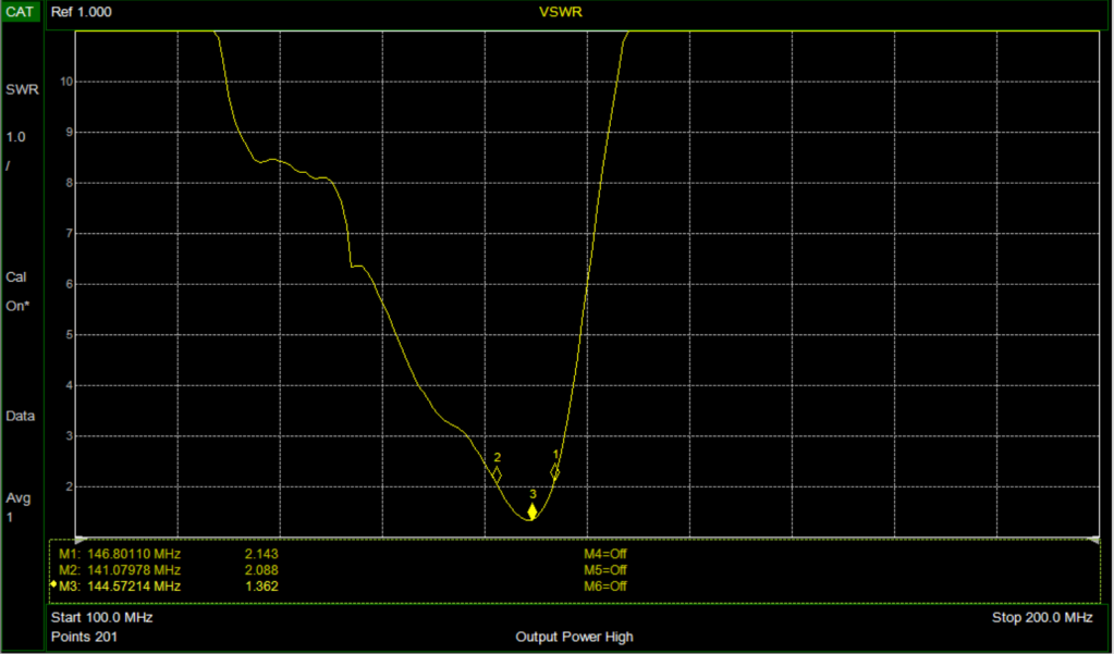
Resonant frequency of 144.57 MHz!
So I guess I got somewhere close. I hope you learned from my methods of trial and error, and please comment if you disagree or have more suggestions for antenna modeling. I’m very receptive. Also very lost.
Further, I will model a loop antenna and a computer-designed log periodic on EZNEC. The log periodic uses transmission lines on EZNEC and stub-matching techniques. I look forward to learning more from these designs.