Signal Exploitation in GNU Radio
This is a follow-up from my past constructive/destructive interference post, where I actually got to apply some of my theory and signal knowledge to a constructive interference attack. Code

DISCLAIMER
I am operating under the FCC Part 15 Rule for my experimental transmitter. I never transmitted more than a few milliwatts and had a range well under 3 meters. Any higher-powered signal contained my callsign at least every 30 seconds.
Theory
Interference is the mixing of two signals to produce a modulated output signal. This is best explained in pictures:


Constructive Interference (Left) and Destructive Interference (Right)
The goal of this project was to eliminate a signal as stated before. Judging by the two images, destructive interference would make more sense for this application initially. However, transmitting the inverse of a signal has intense timing requirements that make it almost impossible for any computational microprocessor. Constructive interference actually has a better chance at distorting the signal - it overly saturates the amplitudes in such a way that the resultant signal is irretrievable.
If used for a PPM signal such as a remote-control device, constructive interference would both saturate the receiver and render any commands incoherent. Additionally, it does not require excess spurious power transmission where destructive interference needs the exact opposite amount.
Constructive Interference also minimizes spectrum signature since it only selectively transmits; a jammer would be active and wide-band at all times.
Overall, my experimental setup looked like the following:

Implementation
For this implementation, I tried to keep as basic and low-power as possible. For the best chance of decoding and reception, I transmitted FM morse code (Continuous wave) with a microcontroller board on the VHF spectrum. I had a simultaneous transmitter-receiver with the Ettus E310 within 1m of the microcontroller. I implemented a GNUradio script to launch the constructive interference attack, and recorded the results using an RTL-SDR to a .dat file. I then analyzed the signal in MATLAB.
Initially, I used a HackRF with the PortaPack attachment to view my signal remotely. However, the interface was a bit tough to use and prone to crashing. Recording the signal with the RTL was relatively pain-free (as explained later) . I followed these instructions to get set up.

Testing Setup w/ CW Waterfall Display
Range is incredibly important in this setup. Power must be kept to a minimum, but the antenna must be at an optimal range for reception, away from near-field effects and metal reflection. An anechoic chamber would be best, but for now a noisy hamshack will do.
Below is the final code I used for the constructive attack.
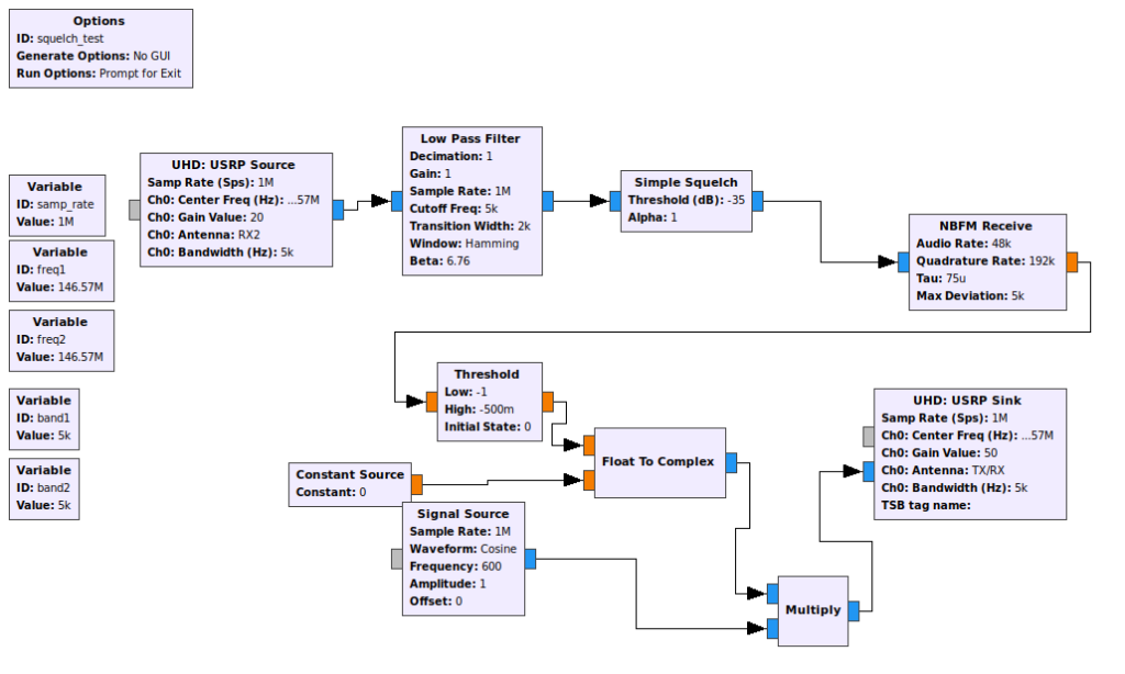
Code for CI Attack. Note squelch/gain values
Challenges
Gain
As stated before, gain was the most challenging aspect of this project. I wanted my microcontroller to be close to the receiving antenna and the attacking device, but oversaturating the receiver meant unusable results. Perhaps attenuating the receiver itself (through changing the electric length of the antenna) would lead to decreased antenna gain and better reception. My initial reception of the frequency-modulated, CW signal looked like this:

Initial CW Signal at 20dB Antenna Gain
Eventually I used the lowest amount of gain on the antenna, 0dB. It gave me a usable signal shown below. To capture it I used this command on the CMD line on my PC:
rtl_sdr -f 146570000 -n 16000000 -s 3200000 -g 0.0 data.dat

FM Morse Code!
After this, I was able to get readable results.
E310 Transmission
Using the E310 was such a pain until it eventually worked. Our issue involved software versions between our internet machine (an intel NUC) and the UHD software on the Ettus. Code on the E310 must actually be compiled, so the programmer has to build programs on a separate computer, generate the python file, and move it over to the networked Ettus. As a test I made a standard cosine wave, then a repeater to show that my device was working. I still had the same conditions for transmission where I was transmitting extremely low power within 1 meter.

Cosine Wave from Ettus

Repeater Function from ID’ed CW Message
Results
Once I figured out the gain variables on the squelch, source, threshold, and sink blocks, I was able to control my interference selectively. I moved the transmit frequency down to the same frequency as the microcontroller and recorded the results. Below are several graphs to show the difference between the control signal (without interference) and the test signal (with interference).
The control signal is identical to the test signal except it lacks any sort of interference. It was still subject to path loss and atmospheric noise, and recorded with the same gain as the test signal.

Raw input from receiver for 10-second sample. Note the change in amplitude and pattern.
After finding the raw signal, I used a matched filter to isolate my cw signal. Surprisingly, with frequency modulation, the morse code portions are the signals with a relative amplitude closer to zero. They have a lower frequency than the spurious emissions - the higher and lower amplitudes.

Filter for CW and exploited signal
The filter used in this experiment completely failed to recognize a usable pattern with the test signal.

FFT of Both Signals
Lastly, a FFT for both signals confirmed what was shown in the previous two; the test signal has no discernable qualities. Therefore it cannot be decoded, and the experiment was successful with the parameters I put in.
UPDATE: 12NOV
I ran the control and experimental tests again to see any variation. It still looks like my code needs work. The raw signals look promising:

Raw Data for Experiment
But the filter seems to work just the same on both frequencies. However, CW is easily recognizable. With PPM, 1’s and 0’s are subject to greater standards; they must remain within a decibel limit and have a specified duration. Those standards do not exist for CW.

Filtered Output
The FFT of the signals did not yield anything significant. Here are the three plots overlaid:
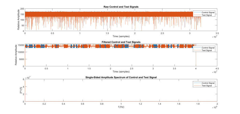
Overlay Plots
You can clearly see the presence of a noisy signal, but not much else has changed with it. It is still able to be decoded by sight. Perhaps a PPM implementation will have more success.
Conclusion
A constructive interference test was created on CW signals for a remote-control pulse-position modulation (PPM) implementation. The experimental setup used GNUradio and an Ettus E-310 to successfully limit decoding of a test beacon signal.
In future tests, I will play around with the gain more to find a custom-tailored result. Even further, I may use an algorithm described in a previous post on ADS-B transmission to dynamically change my threshold values since ADS-B has multiple inputs.
Lastly, I will perform more than a subjective analysis on the transmission. I want to perform a bit-error analysis (BER) as described previously, but am having trouble decoding the FM CW signal through matlab. For future experiments, I plan on synthesizing my own PPM signal and transmitting it through a HackRF instead of the microcontroller. Then, the Ettus will easily be able to intercept and interfere with the signal. Using matlab I will actually be able to determine what percent of bits were intercepted.
Overall this project was incredibly intensive and constructive to the theory behind interferences with a detailed, multidisciplined coding application!