BPSK Revisited: Modulation and Demodulation
In my most recent post, I was able to encode and send binary ascii messages via MATLAB. My output was just a 1x280-bit vector with data points along it, resulting in either the BPSK wave or the B-FSK (binary frequency-shift keying) wave. However, this week I tackled demodulation and found many errors in my previous code. Enjoy!

Intro to Beancounting
BPSK Overview
Once again I will be taking from Wayne Tomasi’s Electronic Communication Systems: Fundamentals Through Advanced. I kept right at page 500-501 in the 1988 edition; the sections on BPSK modulation and demodulation. The book is a fantastic in-depth overview to modulation schemes, and I hope to use it for other applications. If you get bored of digital processing, there are sections on antenna propagation and even TDoA.
All BPSK does is modulate (change) the phase of a signal. In the binary case, it is either π or 0. This means the signal can only be sin(ωt) or -sin(ωt) with a sine reference.
BPSK can be elevated to QPSK; quadrature phase-shift keying. This is a little hard to explain. Basically, signals can have positive or negative, real or imaginary components independent of time. In BPSK, the signal only goes from (1,0) to (-1,0) and back and forth. In QPSK, the signal can be (1, i1), (-1, i1), (-1, -i1), (1, -i1). Now it has four possibilities. Below is an illustration of it, where Q (quadrature) is the imaginary portion, and I is the real (in-phase) portion:
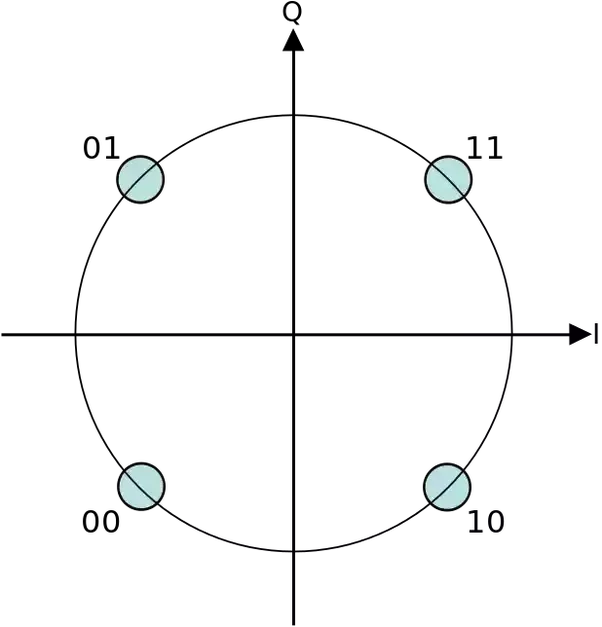
QPSK. Four Possibilities.
You’ll have to wait at least a week for me to try to modulate this way.
Improvements on Code
If you remember last week, this was my finished product for BPSK and B-FSK:
Last Week’s “finished” product
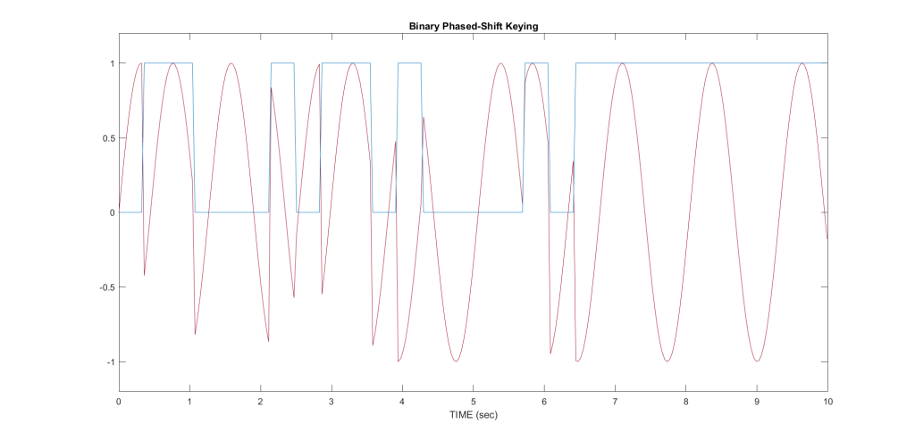
So it looks good enough lined up with the binary bit stream. However, my phase shifts are extremely off. The signal should be a smooth flow, and here I have a lot of “clock pulses;” areas where the phase shifts so rapidly there is an incredibly steep slope. I had to readjust my frequency within my signal (double it if I recall correctly), and I got a much more beautiful signal:
![]()
This all looks much better. At each clock pulse, the sine wave intersects the time axis.
MATLAB Binary encoding
As an aside, I noticed matlab did some odd things with binary encoding. I would get the same signal I transmitted, but it would be incomprehensible garbage. I learned my code for transforming text string to ascii binary vectors was deeply flawed:
%old version of binary encoding
string = 'test';
unicodeValues = double(string);
b = de2bi(unicodeValues);

b = reshape(b,1, []);
This code results in a binary bit stream completely backwards from my input; if I put 0000001, I would receive 1000000. This code fixes it:
%improved binary code
string1 = 'test';
b = flip(de2bi(double(string1)),2);

b = reshape(b.',1, []);
Just a weird matlab tick I saw. It must be something with MSB/LSB encoding.
Demodulation
Now I have my output sine wave, and I want to decode it. The first step was to find the period of the signal and create a carrier (clock) wave. I had to interpolate from the wave I received because I wouldn’t truly know the frequency or duration in an actual receiver. The findpeaks function helped with this, although I used it on the absolute values of my signal. It looked like this:
z2 = abs(zz) %take the absolute value of received wave
[pks, locs] = findpeaks(z2);

T = length(pks);
 %the length of total peaks are the period.

ts = 0:(1/T):10 %generate a vector the total length of the transmission.
From here I used a detection scheme called a product detector.
test_signal = sin(pi*T/10*ts) %clock/carrier frequency

product_detector = test_signal.*zn %product detector
The output of the product detector is actually kind of beautiful. It turns my BPSK into almost pulse-position modulation:

On Top: BPSK with carrier wave. Bottom: Product dete_c_tor with clock signal
So all I had to do from here was threshold the wave bit-by-bit.
bitstream = zeros(1,length(product_detector));
 %empty vector
for i=1:length(product_detector)

    if product_detector(i) > 0
        bitstream(i) = 1
    end

    if product_detector(i) <= 0
         bitstream(i) = 0
    end

end

binary_data = bitstream(5:10:end) %downsample to the middle bit
I chose to use (i <= 0) = 0 because of my carrier wave. Using a cosine or -sine may yield different results.
Decoding
The binary-stream to actual text was a lot of beancounting. I fed the single vector through a couple loops, and used the modulus function to determine whether or not I had a new ascii character. I assumed only lowercase ascii characters would be transmitted; resulting in 7 bits per character.
for i=1:length(binary_data)
  temp_vector = [temp_vector, binary_data(i)]
 %add bit into vector
  if (mod(i,7) == 0)
 %if bit is start of new character
      final_binary = [final_binary; temp_vector]
 %new column
      temp_vector = [];
 %clear register
  end
end
Finally, used some conversion magic and my data popped out!
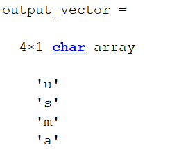
Success
Improvements: Bit length, AWGN, and encryption
To test my robustness as an actual system, I added some gaussian white noise and a filter to my system. It was sort of like throwing a ball into the air and catching it back down; the minimal flight time was just enough to show my system worked. It worked great at an SNR of 20:
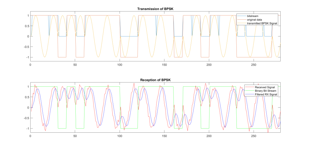
Reception of BPSK with AWGN @ 20
My next step here is to add a better detection of period. Sometimes my bits will be off by 1, resulting in a whole cache of errors. With a 10-second, 4 letter pulse I do not usually have problems.
Encryption can also be a fun side project. The bitstream is already in binary, so RSA / AES / OTPs are pretty easy to implement. Just need a secure way to send the keys…
Conclusion
I learned a lot from beancounting, arrays, vectors, and signal detection in this exercise. It’s the equivalent of a home-improvement weekend project for signals people; pretty fun to set up and play with all within a week. I will probably try more mod/demod products like this, such as FM, next week. Stay tuned!